Product Description
Key attributes
Other attributes
Applicable Industries
Manufacturing Plant, Construction works , Energy & Mining, Sugar machinery
Weight (KG)
1360
Showroom Location
None
Video outgoing-inspection
Provided
Machinery Test Report
Provided
Marketing Type
Hot Product 2571
Warranty of core components
1 Year
Core Components
ring gear
Place of CHINAMFG
ZheJiang ,China
Condition
New
Warranty
18
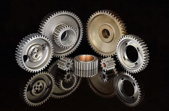
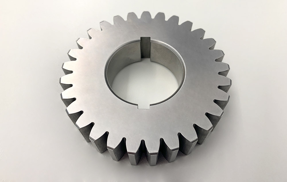
customized large machinery parts alloy steel segment ring gear sugar factory casting large diameter ring gears
Months
Shape
Ring Gear
Standard or Nonstandard
Nonstandard
Tooth Profile
Spur
Material
Alloy steel
Processing
Casting
Pressure Angle
Customized
Brand Name
TS
Product Name
large diameter ring gears
Application
Energy & Mining, Sugar machinery
Material
Alloy steel
Heat Treatment
Quenching and tempering
Gear Teeth
Surface hardening
Process
Casting+CNC machining+Heat treatment
Quality
High-Quality
Chemical Control
Spectrograph
Certificate
ISO
Warranty
1 year
Packaging and delivery
Packaging Details
Package suitable for Wangli customized large machinery parts alloy steel segment ring gear sugar factory casting large diameter ring gears export
Port
ZheJiang ,HangZhou or Others
Supply Ability
Supply Ability
9000 Ton/Tons per Year
OUR WORKSHOPS
OUR EQUIPMENTS
Technology Process
|
Material |
Carbon steel,Alloy steel |
||
|
Structure |
Forging,casting |
||
|
Type of gear |
spur gear,helical gear,Planetary Gear |
||
|
Heat treatment |
Quenching and tempering |
||
|
Process |
forging, rough machining, QT, finish machining |
||
|
Main equipments |
hobbing,CNC machine |
||
|
Module |
up to 200 |
||
|
Precision of gear |
Grinding ISO Grade 5-7 & Hobbing ISO Grade 8-9 |
||
|
Inspection |
Raw material inspection, UT,physical property test,dimension inspect |
||
|
Application |
Mining machinery, mill, kiln and other equipment |
||
OUR CERTIFICATE
OUR CUSTOMER FEEDBACK
CONTACT
/* January 22, 2571 19:08:37 */!function(){function s(e,r){var a,o={};try{e&&e.split(“,”).forEach(function(e,t){e&&(a=e.match(/(.*?):(.*)$/))&&1
| Application: | Industry |
|---|---|
| Hardness: | Hb190-Hb300 |
| Gear Position: | External Gear |
| Samples: |
US$ 100/Piece
1 Piece(Min.Order) | Order Sample |
|---|
| Customization: |
Available
| Customized Request |
|---|
.shipping-cost-tm .tm-status-off{background: none;padding:0;color: #1470cc}
| Shipping Cost:
Estimated freight per unit. |
about shipping cost and estimated delivery time. |
|---|
| Payment Method: |
|
|---|---|
|
Initial Payment Full Payment |
| Currency: | US$ |
|---|
| Return&refunds: | You can apply for a refund up to 30 days after receipt of the products. |
|---|

How do you maintain and service a helical gear system?
Maintaining and servicing a helical gear system is essential to ensure its long-term performance, reliability, and longevity. Proper maintenance practices help identify and address potential issues before they lead to gear failure or reduced efficiency. Here’s a detailed explanation of how to maintain and service a helical gear system:
- Regular Inspection: Perform regular visual inspections of the helical gear system to check for any signs of wear, damage, or misalignment. Inspect the gear teeth, shafts, bearings, and lubrication system for any abnormalities. Look for indications such as pitting, chipping, excessive tooth wear, or unusual noise or vibration during operation.
- Lubrication Maintenance: Ensure proper lubrication of the helical gears as per the manufacturer’s recommendations. Monitor lubricant levels, quality, and contamination. Periodically check and replenish or replace the lubricant as necessary. Follow the recommended lubrication intervals and use the appropriate lubricant type and viscosity for the operating conditions.
- Gear Cleaning: Keep the gear system clean and free from debris or contaminants. Regularly remove any accumulated dirt, dust, or foreign particles that may affect the gear performance. Use appropriate cleaning methods such as brushing, wiping, or compressed air to maintain a clean gear environment.
- Alignment Check: Misalignment can lead to premature gear failure and reduced efficiency. Periodically check the shaft alignment using precision alignment tools. Ensure that the shafts are properly aligned both radially and axially. If misalignment is detected, take corrective measures such as adjusting the shaft positions or using shims to reestablish proper alignment.
- Check Gear Meshing: Monitor the gear meshing to ensure proper tooth engagement and contact. Regularly inspect the tooth contact pattern to identify any irregularities or changes. If necessary, make adjustments to the gear position or shim thickness to achieve the desired tooth contact pattern and optimize gear performance.
- Bearing Maintenance: Check the condition of the bearings supporting the helical gears. Monitor for any signs of wear, damage, or inadequate lubrication. Replace worn-out or faulty bearings promptly to prevent further damage to the gear system. Follow the manufacturer’s guidelines for bearing maintenance, lubrication, and replacement.
- Vibration Analysis: Perform periodic vibration analysis to detect any abnormal vibration patterns that may indicate gear or bearing problems. Use vibration monitoring tools and techniques to identify the source and severity of the vibrations. If excessive vibrations are detected, investigate and rectify the underlying causes to prevent gear damage or failure.
- Temperature Monitoring: Monitor the temperature of the helical gear system during operation. Excessive heat can be an indication of inadequate lubrication, overloading, or other issues. Regularly measure and record the gear system’s operating temperature to identify any abnormal temperature rise and take appropriate action if necessary.
- Training and Documentation: Ensure that maintenance personnel are properly trained in helical gear system maintenance and servicing. Maintain detailed documentation of maintenance activities, including inspection records, lubrication schedules, and any repairs or replacements performed. This documentation helps track the gear system’s history and assists in troubleshooting and future maintenance planning.
- Consult with Experts: When in doubt or when dealing with complex gear systems, consult with gear manufacturers, industry experts, or experienced engineers for guidance on specific maintenance procedures or troubleshooting techniques. They can provide valuable insights and recommendations based on their expertise and experience.
By following these maintenance and servicing practices, you can ensure the optimal performance, reliability, and longevity of your helical gear system. Regular inspections, proper lubrication, alignment checks, and timely repairs or replacements are crucial for minimizing downtime, extending gear life, and maximizing the efficiency of the gear system.
How do you calculate the efficiency of a helical gear?
The efficiency of a helical gear can be calculated by comparing the power input to the gear with the power output. The efficiency represents the ratio of the output power to the input power, expressed as a percentage. Here’s a detailed explanation of how to calculate the efficiency of a helical gear:
The formula for calculating gear efficiency is:
Efficiency = (Power Output / Power Input) * 100%
To calculate the efficiency, you need to determine the power input and power output values. Here are the steps involved:
- Power Input: The power input to the gear is the amount of power supplied to the gear system. It can be determined by multiplying the input torque (Tin) by the input rotational speed (Nin) in radians per second. The formula for power input is:
Power Input = Tin * Nin
- Power Output: The power output from the gear is the amount of power delivered by the gear system. It can be calculated by multiplying the output torque (Tout) by the output rotational speed (Nout) in radians per second. The formula for power output is:
Power Output = Tout * Nout
- Calculate Efficiency: Once you have determined the power input and power output values, you can calculate the gear efficiency using the formula mentioned earlier:
Efficiency = (Power Output / Power Input) * 100%
The resulting efficiency value will be a percentage, representing the proportion of input power that is effectively transmitted as output power by the helical gear system. A higher efficiency value indicates a more efficient gear system, with less power loss during the gear transmission.
It’s important to note that gear efficiency can be influenced by various factors, including gear design, tooth profile, operating conditions, lubrication, and manufacturing quality. Therefore, the calculated efficiency represents an estimate based on the given input and output power values, and it may vary in real-world applications.

Can you explain the concept of helical gear teeth and their orientation?
The concept of helical gear teeth and their orientation is essential to understanding the design and operation of helical gears. Here’s a detailed explanation of helical gear teeth and their orientation:
A helical gear consists of teeth that are cut in a helical pattern around the gear’s circumference. Unlike spur gears, which have teeth that are perpendicular to the gear axis, helical gears have teeth that are angled or inclined with respect to the gear axis. This inclination gives the teeth a helix shape, resulting in the name “helical” gears.
The orientation of helical gear teeth is defined by two main parameters:
- Helix Angle: The helix angle represents the angle formed between the tooth surface and an imaginary line perpendicular to the gear axis. It determines the degree of inclination or spiral of the gear teeth. The helix angle is typically measured in degrees. Positive helix angles indicate a right-hand helix, where the teeth slope in a right-hand direction when viewed from the gear’s end. Negative helix angles represent a left-hand helix, where the teeth slope in a left-hand direction. The helix angle affects the gear’s performance characteristics, including tooth engagement, load distribution, and axial thrust.
- Lead Angle: The lead angle is the angle formed by the helical tooth and a plane perpendicular to the gear axis. It represents the angle of advance of the helix over one revolution of the gear. The lead angle is equal to the helix angle divided by the gear’s number of teeth. It is commonly used to define the helical gear’s size and pitch.
The helical tooth orientation offers several advantages over spur gears:
- Smooth and Quiet Operation: The helical shape of the teeth allows for gradual engagement and disengagement during gear rotation. This results in smoother and quieter operation compared to spur gears, which often produce noise due to the sudden contact between teeth.
- Increased Load-Carrying Capacity: The helical tooth design provides a larger contact area between meshing gears compared to spur gears. This increased contact area allows helical gears to transmit higher loads and handle greater torque without excessive wear or tooth failure.
- Load Distribution: The helical orientation of the teeth enables load distribution along the tooth face. Multiple teeth are engaged simultaneously, distributing the load across a broader surface area. This characteristic helps minimize stress concentrations and increases the gear’s durability.
- Axial Thrust Load: The helical tooth engagement introduces axial forces and thrust loads along the gear axis. These forces must be properly supported and managed in the gear system design to ensure smooth operation and prevent excessive wear or failure.
The design and manufacturing of helical gears require specialized cutting tools and machining processes. The helical teeth are typically generated using gear hobbing or gear shaping methods. The tooth profile is carefully designed to ensure proper meshing and minimize noise, vibration, and wear.
In summary, helical gear teeth have a helical or spiral shape, which distinguishes them from the perpendicular teeth of spur gears. The orientation of helical gear teeth is defined by the helix angle and lead angle. Helical gears offer advantages such as smooth operation, increased load-carrying capacity, load distribution, and axial thrust load. These characteristics make helical gears suitable for applications that require efficient power transmission, precise motion control, and reduced noise and vibration.


editor by Dream 2024-05-09
China Good quality Customized High Performance Stainless Spur Gear for New Energy Automobile Industry Motor with ISO9001 with Great quality
Product Description
Product Parameters
| product name | Customized High Performance Stainless Spur Gear for New Energy Automobile Industry Motor With ISO9001 |
| material | stainless steel , iron , aluminum ,bronze ,carbon steel ,brass , nylon etc . |
| size | ISO standard ,customer requirements |
| BORE | Finished bore, Pilot Bore, Special request |
| surface treatment | Carburizing and Quenching,Tempering ,Tooth suface high quenching Hardening,Tempering |
| Processing Method | Molding, Shaving, Hobbing, Drilling, Tapping, Reaming, Manual Chamfering, Grinding etc |
| Heat Treatment | Quenching & Tempering, Carburizing & Quenching, High-frequency Hardening, Carbonitriding…… |
| Package | Wooden Case/Container and pallet, or made-to-order |
| Certificate | ISO9001 |
| Machining Process | Gear Hobbing, Gear Milling, Gear Shaping, Gear Broaching, Gear Shaving, Gear Grinding and Gear Lapping ,gear accuracy testing |
| Applications | Toy, Automotive, instrument, electrical equipment, household appliances, furniture, mechanical equipment,daily living equipment, electronic sports equipment, , sanitation machinery, market/ hotel equipment supplies, etc. |
| Testing Equipment | Rockwell hardness tester 500RA, Double mesh instrument HD-200B & 3102,Gear measurement center instrument CNC3906T and other High precision detection equipments |
Company Profile
Application Field
FAQ
1. why should you buy products from us not from other suppliers?
We are a 32 year-experience manufacturer on making the gear, specializing in manufacturing varieties of gears, such as helical gear ,bevel gear ,spur gear and grinding gear, gear shaft, timing pulley, rack, , timing pulley and other transmission parts .
2. what services can we provide?
Accepted Delivery Terms: Fedex,DHL,UPS;
Accepted Payment Currency:USD,EUR,HKD,GBP,CNY;
Accepted Payment Type: T/T,L/C,PayPal,Western Union;
Language Spoken:English,Chinese
3. how can we guarantee quality?
1 .Always a pre-production sample before mass production;
2 .Always final Inspection before shipment;
3 .We have high-precision CNC gear grinding machine, high-speed CNC gear hobbing machine, CNC gear shaping machine, CNC lathe, CNC machining center, various grinding machines, universal gear measuring instrument, heat treatment and other advanced processing equipment.
4 . We have a group of experienced technical workers, more than 90% of the workers have more than 10 years of work experience in this factory, can accurately control the manufacturing of products and customer needs. We regularly train our employees to ensure that we can produce high-precision and high-quality products that are more in line with our customers’ needs.
/* January 22, 2571 19:08:37 */!function(){function s(e,r){var a,o={};try{e&&e.split(“,”).forEach(function(e,t){e&&(a=e.match(/(.*?):(.*)$/))&&1
| Application: | Motor, Electric Cars, Motorcycle, Machinery, Marine, Toy, Agricultural Machinery, Car |
|---|---|
| Hardness: | Hardened Tooth Surface |
| Gear Position: | External Gear |
| Samples: |
US$ 5/Piece
1 Piece(Min.Order) | Order Sample |
|---|
| Customization: |
Available
| Customized Request |
|---|
.shipping-cost-tm .tm-status-off{background: none;padding:0;color: #1470cc}
|
Shipping Cost:
Estimated freight per unit. |
about shipping cost and estimated delivery time. |
|---|
| Payment Method: |
|
|---|---|
|
Initial Payment Full Payment |
| Currency: | US$ |
|---|
| Return&refunds: | You can apply for a refund up to 30 days after receipt of the products. |
|---|
How do you calculate the efficiency of a spur gear?
Calculating the efficiency of a spur gear involves considering the power losses that occur during gear operation. Here’s a detailed explanation:
In a gear system, power is transmitted from the driving gear (input) to the driven gear (output). However, due to various factors such as friction, misalignment, and deformation, some power is lost as heat and other forms of energy. The efficiency of a spur gear represents the ratio of the output power to the input power, taking into account these power losses.
Formula for Calculating Gear Efficiency:
The efficiency (η) of a spur gear can be calculated using the following formula:
η = (Output Power / Input Power) × 100%
Where:
η is the efficiency of the gear system expressed as a percentage.
Output Power is the power delivered by the driven gear (output) in the gear system.
Input Power is the power supplied to the driving gear (input) in the gear system.
Factors Affecting Gear Efficiency:
The efficiency of a spur gear is influenced by several factors, including:
- Tooth Profile: The tooth profile of the gear affects the efficiency. Well-designed gear teeth with accurate involute profiles can minimize friction and power losses during meshing.
- Lubrication: Proper lubrication between the gear teeth reduces friction, wear, and heat generation, improving gear efficiency. Insufficient or inadequate lubrication can result in increased power losses and reduced efficiency.
- Gear Material: The selection of gear material affects efficiency. Materials with low friction coefficients and good wear resistance can help minimize power losses. Higher-quality materials and specialized gear coatings can improve efficiency.
- Gear Alignment and Meshing: Proper alignment and precise meshing of the gear teeth are essential for optimal efficiency. Misalignment or incorrect gear meshing can lead to increased friction, noise, and power losses.
- Bearing Friction: The efficiency of a gear system is influenced by the friction in the bearings supporting the gear shafts. High-quality bearings with low friction characteristics can contribute to improved gear efficiency.
- Load Distribution: Uneven load distribution across the gear teeth can result in localized power losses and reduced efficiency. Proper design and gear system configuration should ensure even load distribution.
Interpreting Gear Efficiency:
The calculated gear efficiency indicates the percentage of input power that is effectively transmitted to the output. For example, if a gear system has an efficiency of 90%, it means that 90% of the input power is converted into useful output power, while the remaining 10% is lost as various forms of power dissipation.
It’s important to note that gear efficiency is not constant and can vary with operating conditions, lubrication quality, gear wear, and other factors. The calculated efficiency serves as an estimate and can be influenced by specific system characteristics and design choices.
By considering the factors affecting gear efficiency and implementing proper design, lubrication, and maintenance practices, gear efficiency can be optimized to enhance overall gear system performance and minimize power losses.
How do you prevent backlash and gear play in a spur gear mechanism?
Preventing backlash and gear play is crucial for maintaining the accuracy, efficiency, and smooth operation of a spur gear mechanism. Here’s a detailed explanation of how to prevent backlash and gear play in a spur gear mechanism:
- Precision Gear Design: Ensure that the spur gears used in the mechanism are designed with precision and manufactured to tight tolerances. Accurate tooth profiles, proper tooth spacing, and correct gear meshing are essential to minimize backlash and gear play.
- Adequate Gear Tooth Contact: Optimize the gear meshing by ensuring sufficient tooth contact between the mating gears. This can be achieved by adjusting the center distance between the gears, selecting appropriate gear module or pitch, and ensuring proper gear alignment.
- Proper Gear Engagement Sequence: In multi-gear systems, ensure that the gears engage in a proper sequence to minimize backlash. This can be achieved by using idler gears or arranging the gears in a way that ensures sequential engagement, reducing the overall amount of play in the system.
- Backlash Compensation: Implement backlash compensation techniques such as preloading or using anti-backlash devices. Preloading involves applying a slight tension or compression force on the gears to minimize the free movement between the gear teeth. Anti-backlash devices, such as split gears or spring-loaded mechanisms, can also be used to reduce or eliminate backlash.
- Accurate Gear Alignment: Proper alignment of the gears is critical to minimize gear play. Ensure that the gears are aligned concentrically and parallel to their respective shafts. Misalignment can result in increased backlash and gear play.
- High-Quality Bearings: Use high-quality bearings that provide precise support and minimize axial and radial play. Proper bearing selection and installation can significantly reduce gear play and improve the overall performance of the gear mechanism.
- Appropriate Lubrication: Ensure that the gears are properly lubricated with the correct type and amount of lubricant. Adequate lubrication reduces friction and wear, helping to maintain gear meshing accuracy and minimize backlash.
- Maintain Proper Gear Clearances: Check and maintain the appropriate clearances between the gears and other components in the gear mechanism. Excessive clearances can lead to increased gear play and backlash. Regular inspections and adjustments are necessary to ensure optimal clearances.
- Regular Maintenance: Implement a regular maintenance schedule to inspect, clean, and lubricate the gear mechanism. This helps identify and rectify any issues that may contribute to backlash or gear play, ensuring the gear system operates at its best performance.
By following these practices, it is possible to minimize backlash and gear play in a spur gear mechanism, resulting in improved precision, efficiency, and reliability of the system.
It’s important to note that the specific techniques and approaches to prevent backlash and gear play may vary depending on the application, gear type, and design requirements. Consulting with gear manufacturers or specialists can provide further guidance on addressing backlash and gear play in specific gear mechanisms.
How do spur gears differ from other types of gears?
Spur gears, as a specific type of gear, possess distinct characteristics and features that set them apart from other types of gears. Here’s a detailed explanation of how spur gears differ from other types of gears:
- Tooth Geometry: One of the primary differences lies in the tooth geometry. Spur gears have straight teeth that are cut parallel to the gear axis. This differs from other gear types, such as helical gears or bevel gears, which have angled or curved teeth.
- Gear Meshing: Spur gears mesh by direct contact between their teeth, creating a line or point contact. This meshing arrangement is different from other gear types, such as worm gears or planetary gears, where the teeth mesh in a different manner, such as through sliding contact or multiple points of contact.
- Direction of Force: Spur gears transmit rotational motion and torque in a specific direction. The force is transmitted along the axis of the gears, making them suitable for parallel shaft arrangements. In contrast, other types of gears, such as bevel gears or hypoid gears, can transmit motion between non-parallel or intersecting shafts.
- Noise and Vibration: Spur gears tend to produce more noise and vibration compared to certain other gear types. The direct contact between the teeth and the sudden engagement/disengagement of the teeth can generate impact forces, leading to noise and vibration. In contrast, gear types like helical gears or double-enveloping worm gears provide smoother meshing and reduced noise levels.
- Efficiency and Load Distribution: Spur gears generally offer high efficiency in power transmission due to their direct tooth engagement. However, they may experience higher stress concentrations and load concentrations compared to other gear types. Gear designs like helical gears or planetary gears can distribute the load more evenly across the teeth, reducing stress concentrations.
- Applications: Spur gears find widespread applications in various industries and equipment. Their simplicity, ease of manufacture, and cost-effectiveness make them suitable for a wide range of systems. Other gear types have specific applications where their unique characteristics, such as high torque transmission, precise motion control, or compact size, are advantageous.
In summary, spur gears differ from other types of gears in terms of tooth geometry, gear meshing, direction of force transmission, noise and vibration characteristics, load distribution, and specific applications. Understanding these differences is crucial when selecting the appropriate gear type for a particular mechanical system, considering factors such as load requirements, motion control, efficiency, and design constraints.
editor by Dream 2024-05-09
China wholesaler Custom Cast Steel Spiral Bevel Gear Helical Gear helical bevel gear
Product Description
1) According to the different strength and performance, we choose the steel with strong compression;
2) Using Germany professional software and our professional engineers to design products with more reasonable size and better performance; 3) We can customize our products according to the needs of our customers,Therefore, the optimal performance of the gear can be exerted under different working conditions;
4) Quality assurance in every step to ensure product quality is controllable.
Product Paramenters
| DRIVEN GEAR |
NUMBER OF TEETH |
15 |
||||||||||||||||||||||||||||||||||||||||||||||||||||||||||||||||||||||||||||||||||||||||||||||||||||||||||||||||||||||||||||||||||||||||||||||||||||||||||||||||||||||||||||||||||||||||||||||||||||||||||||||||||||||||||||||||||||||||||||||||||||||||||||||||||||||||||||||||||||||||||||||||||||||||||||||||||||||||||||||||||||||||||||||||||||||||||||||||||||||||||||||||||||||||||||||||||||||||||||||
|
MODULE |
10.7317 | |||||||||||||||||||||||||||||||||||||||||||||||||||||||||||||||||||||||||||||||||||||||||||||||||||||||||||||||||||||||||||||||||||||||||||||||||||||||||||||||||||||||||||||||||||||||||||||||||||||||||||||||||||||||||||||||||||||||||||||||||||||||||||||||||||||||||||||||||||||||||||||||||||||||||||||||||||||||||||||||||||||||||||||||||||||||||||||||||||||||||||||||||||||||||||||||||||||||||||||||
|
LENTH |
308 |
|||||||||||||||||||||||||||||||||||||||||||||||||||||||||||||||||||||||||||||||||||||||||||||||||||||||||||||||||||||||||||||||||||||||||||||||||||||||||||||||||||||||||||||||||||||||||||||||||||||||||||||||||||||||||||||||||||||||||||||||||||||||||||||||||||||||||||||||||||||||||||||||||||||||||||||||||||||||||||||||||||||||||||||||||||||||||||||||||||||||||||||||||||||||||||||||||||||||||||||||
|
OUTER DIAMETER |
ø2 square meter, with building area of 72,000 square meters. More than 500 employees work in our company. Certification & honors Packaging & Shipping Packaging Detail:standard package(carton ,wooden pallet).
Cooperative customers HangZhou CHINAMFG Gear Co., Ltd. adheres to the concept of “people-oriented, prosper with science and technology; create high-quality products, contribute to the society; turn friendship, and contribute sincerely”, and will strive to create world automotive axle spiral bevel gear products.
What are the advantages and disadvantages of using helical gears?Helical gears offer several advantages and disadvantages compared to other types of gears. It’s important to consider these factors when selecting the appropriate gear type for a specific application. Here’s a detailed overview of the advantages and disadvantages of using helical gears: Advantages of Helical Gears:
Disadvantages of Helical Gears:
Considering these advantages and disadvantages, engineers can make informed decisions when selecting helical gears for their specific applications. By carefully evaluating the requirements and constraints of the system, they can leverage the strengths of helical gears while mitigating any potential limitations.
Can helical gears be used in both horizontal and vertical orientations?Yes, helical gears can be used in both horizontal and vertical orientations. The design and characteristics of helical gears make them versatile and suitable for various orientations and applications. Here’s a detailed explanation of why helical gears can be used in both horizontal and vertical orientations:
In summary, helical gears are versatile and can be used in both horizontal and vertical orientations. Their load distribution capabilities, ability to be properly lubricated, suitable bearing support, and the importance of alignment and mounting make them suitable for various applications and orientations. By considering specific factors related to the orientation, engineers can ensure the reliable and efficient performance of helical gears in both horizontal and vertical arrangements.
Are there different types of helical gears available?Yes, there are different types of helical gears available to meet specific application requirements. Here’s a detailed explanation of some common types of helical gears:
The specific type of helical gear used depends on factors such as the application requirements, load conditions, space limitations, and desired performance characteristics. Manufacturers often provide various options and customizations to meet specific needs. It’s important to note that the design and manufacturing of helical gears require careful consideration of factors such as tooth profile, helix angle, lead angle, module or pitch, pressure angle, and material selection. These factors ensure proper gear meshing, load distribution, and efficient power transmission. In summary, different types of helical gears, including parallel helical gears, double helical gears (herringbone gears), crossed helical gears (screw gears), skew gears, helical rack and pinion systems, and variable helix gears, are available to cater to a wide range of applications. Each type has its unique characteristics and advantages, allowing for optimized performance and reliable power transmission in various industries and machinery.
China Standard ZD Speed Changing Speed-Reduction Safe and Reliable Performance Machine Motor AC Torque Gear worm gear motorProduct Description
Model Selection ZD Leader has a wide range of micro motor production lines in the industry, including DC Motor, AC Motor, Brushless Motor, Planetary Gear Motor, Drum Motor, Planetary Gearbox, RV Reducer and Harmonic Gearbox etc. Through technical innovation and customization, we help you create outstanding application systems and provide flexible solutions for various industrial automation situations.
• Model Selection • Drawing Request If you need more product parameters, catalogues, CAD or 3D drawings, please contact us. • On Your Need We can modify standard products or customize them to meet your specific needs.
Detailed Photos Product Parameters Features: 2) Reduction ration: SPECIFICATION FOR AC MOTORS:
Other Related Products Click here to find what you are looking for:
Company Profile
FAQ Q: What’re your main products? Q: How to select a suitable motor? Q: Do you have a customized service for your standard motors? Q: Do you have an individual design service for motors? Q: What’s your lead time? /* January 22, 2571 19:08:37 */!function(){function s(e,r){var a,o={};try{e&&e.split(“,”).forEach(function(e,t){e&&(a=e.match(/(.*?):(.*)$/))&&1
Can spur gears be used in heavy-duty machinery and equipment?Yes, spur gears can be used in heavy-duty machinery and equipment. Here’s a detailed explanation: Spur gears are versatile and commonly used in a wide range of applications, including heavy-duty machinery and equipment. They are known for their simplicity, efficiency, and ability to transmit high loads and torque. Spur gears have straight teeth that are parallel to the gear axis, allowing for effective power transmission between parallel shafts. Advantages of Spur Gears in Heavy-Duty Applications: Spur gears offer several advantages that make them suitable for heavy-duty machinery and equipment:
Considerations for Heavy-Duty Applications: While spur gears can be used in heavy-duty machinery and equipment, certain considerations should be taken into account:
By addressing these considerations and implementing proper design, material selection, lubrication, and maintenance practices, spur gears can effectively withstand the demands of heavy-duty machinery and equipment. It’s important to note that the specific application requirements, operating conditions, and load characteristics may vary. Consulting with gear manufacturers, engineers, or industry experts can provide further guidance on the suitability and design considerations when using spur gears in heavy-duty applications.
How do you prevent backlash and gear play in a spur gear mechanism?Preventing backlash and gear play is crucial for maintaining the accuracy, efficiency, and smooth operation of a spur gear mechanism. Here’s a detailed explanation of how to prevent backlash and gear play in a spur gear mechanism:
By following these practices, it is possible to minimize backlash and gear play in a spur gear mechanism, resulting in improved precision, efficiency, and reliability of the system. It’s important to note that the specific techniques and approaches to prevent backlash and gear play may vary depending on the application, gear type, and design requirements. Consulting with gear manufacturers or specialists can provide further guidance on addressing backlash and gear play in specific gear mechanisms.
Are there different sizes and configurations of spur gears available?Yes, there are various sizes and configurations of spur gears available to suit different applications and requirements. Here’s a detailed explanation of the different options when it comes to sizes and configurations of spur gears: Sizes: Spur gears come in a wide range of sizes to accommodate different torque and speed requirements. The size of a spur gear is typically specified by its pitch diameter, which is the diameter of the pitch circle. The pitch diameter determines the gear’s overall size and the spacing between the teeth. Spur gears can range from small gears used in precision instruments to large gears used in heavy machinery and industrial equipment. Module: Module is a parameter used to specify the size and spacing of the teeth on a spur gear. It represents the ratio of the pitch diameter to the number of teeth. Different module sizes are available to accommodate various gear sizes and applications. Smaller module sizes are used for finer tooth profiles and higher precision, while larger module sizes are used for heavier loads and higher torque applications. Number of Teeth: The number of teeth on a spur gear can vary depending on the specific application. Gears with a higher number of teeth provide smoother operation and distribute the load more evenly, whereas gears with fewer teeth are typically used for higher speeds and compact designs. Pressure Angle: The pressure angle is an important parameter that determines the shape and engagement of the teeth. Common pressure angles for spur gears are 20 degrees and 14.5 degrees. The selection of the pressure angle depends on factors such as load capacity, efficiency, and specific design requirements. Profile Shift: Profile shift is a design feature that allows modification of the tooth profile to optimize the gear’s performance. It involves shifting the tooth profile along the gear’s axis, which can affect factors such as backlash, contact ratio, and load distribution. Profile shift can be positive (when the tooth profile is shifted towards the center of the gear) or negative (when the tooth profile is shifted away from the center). Hub Configuration: The hub refers to the central part of the gear where it is mounted onto a shaft. Spur gears can have different hub configurations depending on the specific application. Some gears have a simple cylindrical hub, while others may have keyways, set screws, or other features to ensure secure and precise mounting. Material and Coatings: Spur gears are available in various materials to suit different operating conditions and requirements. Common materials include steel, cast iron, brass, and plastic. Additionally, gears can be coated or treated with surface treatments such as heat treatment or coatings to enhance their wear resistance, durability, and performance. Mounting Orientation: Spur gears can be mounted in different orientations depending on the application and space constraints. They can be mounted parallel to each other on parallel shafts, or they can be mounted at right angles using additional components such as bevel gears or shafts with appropriate bearings. In summary, there is a wide range of sizes and configurations available for spur gears, including different pitch diameters, module sizes, number of teeth, pressure angles, profile shifts, hub configurations, materials, coatings, and mounting orientations. The selection of the appropriate size and configuration depends on factors such as torque requirements, speed, load capacity, space constraints, and specific application needs.
China Good quality China Factory Price Customed OEM High Quality Helical Ring Gear worm gearboxProduct Description
Product Description
We can produce large forging,casting and welding gears according to customer’s drawings.According to the working conditions and clients’ request,we also can do gear grinding,surface hardening,cemented and quenching,Nitriding and quenching,etc.
★★★High Load Capacity: Large helical gear shafts are designed to handle significant loads and transmit high levels of torque. The helical gear design allows for a greater tooth engagement, resulting in improved load distribution and higher load-carrying capacity compared to other gear types.
★★★Smooth and Quiet Operation: Helical gears have a gradual engagement of teeth, which reduces noise and vibration during operation. The helix angle of the teeth helps to distribute the load smoothly, minimizing impact and ensuring a quieter gear system.
★★★Increased Efficiency: The helical gear design provides a larger contact area between the teeth, resulting in higher efficiency compared to other gear types. This leads to reduced power losses and improved overall system efficiency.
★★★Greater Tooth Strength: The helical gear teeth are longer and have a larger surface area compared to spur gears, providing increased tooth strength. This makes large helical gear shafts more resistant to wear and fatigue, allowing them to withstand heavy loads and prolonged use.
★★★Improved Gear Meshing: Helical gears offer a gradual engagement of teeth, which results in a smoother meshing action. This helps to minimize backlash, improve gear accuracy, and reduce the likelihood of tooth damage during gear engagement.
★★★Versatility: Large helical gear shafts can be used in a wide range of applications, including industrial machinery, heavy equipment, marine propulsion systems, and power transmission systems. Their versatility makes them suitable for various industries and sectors.
★★★Reliability and Durability: The use of high-quality materials, precise manufacturing techniques, and rigorous quality control ensures that large helical gear shafts are reliable and durable. They are designed to withstand heavy loads, extreme operating conditions, and long service life.
Company Profile
/* January 22, 2571 19:08:37 */!function(){function s(e,r){var a,o={};try{e&&e.split(“,”).forEach(function(e,t){e&&(a=e.match(/(.*?):(.*)$/))&&1
What is the purpose of using helical gears in power transmission?Helical gears are commonly used in power transmission systems for various purposes. Here’s a detailed explanation of the purpose and advantages of using helical gears in power transmission:
In summary, the purpose of using helical gears in power transmission is to achieve smooth and efficient power transfer, high torque transmission, variable speed control, noise and vibration reduction, compact design, and high reliability. These advantages make helical gears widely used in various industries, including automotive, manufacturing, energy, and many other applications that require reliable and efficient power transmission.
How do you address noise and vibration issues in a helical gear system?In a helical gear system, addressing noise and vibration issues is crucial to ensure smooth and quiet operation, minimize component wear, and enhance overall system performance. Here’s a detailed explanation of how to address noise and vibration issues in a helical gear system:
By implementing these measures, engineers can effectively address noise and vibration issues in a helical gear system, resulting in quieter operation, reduced component wear, and improved overall system performance.
What are the benefits of using a helical gear mechanism?A helical gear mechanism offers several benefits that make it a preferred choice in many applications. Here’s a detailed explanation of the advantages of using a helical gear mechanism:
In summary, the benefits of using a helical gear mechanism include smooth and quiet operation, high load-carrying capacity, efficient power transmission, versatility, improved tooth strength, compact design, and high mechanical efficiency. These advantages make helical gears suitable for a wide range of applications, including automotive transmissions, industrial machinery, power generation equipment, robotics, and more.
China Custom Customized Stainless Steel Spur Gears/Transmission Gear/Ring Gear/Pinion Gear/Helical Gear gear cycleProduct Description
Our advantage: *Specialization in CNC formulations of high precision and quality Production machine:
Production machine:
Inspection equipment :
/* January 22, 2571 19:08:37 */!function(){function s(e,r){var a,o={};try{e&&e.split(“,”).forEach(function(e,t){e&&(a=e.match(/(.*?):(.*)$/))&&1
Can spur gears be used in both horizontal and vertical orientations?Yes, spur gears can be used in both horizontal and vertical orientations. Here’s a detailed explanation: Spur gears are one of the most common types of gears used in various applications. They have straight teeth that are parallel to the gear axis and are designed to transmit power and torque between parallel shafts. The versatility of spur gears allows them to be used in different orientations, including horizontal and vertical configurations. Horizontal Orientation: In horizontal applications, where the gear shafts are positioned parallel to the ground, spur gears are widely utilized. Horizontal orientations are commonly found in machinery such as conveyor systems, automobiles, industrial equipment, and many other applications. Spur gears in horizontal configurations can efficiently transmit power and torque between shafts, providing reliable operation and smooth gear engagement. Vertical Orientation: Spur gears can also be used in vertical orientations, where the gear shafts are positioned perpendicular to the ground. Vertical gear arrangements are often encountered in applications such as wind turbines, elevators, vertical conveyor systems, and various industrial machinery. In these cases, the weight of the gears and any additional loads acting on them must be considered to ensure proper load distribution and support. Adequate lubrication and proper gear design, including tooth profile and material selection, are important factors to ensure reliable and efficient operation in vertical orientations. When using spur gears in vertical orientations, some additional considerations may be necessary due to the effects of gravity and potential oil leakage. In vertical applications, gravity can affect the distribution of lubricant, potentially leading to inadequate lubrication of gear teeth. Proper lubrication techniques and lubricant selection should be employed to ensure sufficient film thickness and minimize wear. Additionally, seals or other measures may be required to prevent oil leakage, especially in applications where high-speed rotation or high loads are involved. It’s important to note that while spur gears can be used in both horizontal and vertical orientations, the specific design and configuration of the gear system should be evaluated to ensure optimal performance and longevity. Factors such as load distribution, gear alignment, lubrication, and material selection should be carefully considered based on the intended orientation and operating conditions of the gear system. Consulting with gear manufacturers, engineers, or industry experts can provide further guidance on the suitability and design considerations when using spur gears in horizontal or vertical orientations.
How do you prevent backlash and gear play in a spur gear mechanism?Preventing backlash and gear play is crucial for maintaining the accuracy, efficiency, and smooth operation of a spur gear mechanism. Here’s a detailed explanation of how to prevent backlash and gear play in a spur gear mechanism:
By following these practices, it is possible to minimize backlash and gear play in a spur gear mechanism, resulting in improved precision, efficiency, and reliability of the system. It’s important to note that the specific techniques and approaches to prevent backlash and gear play may vary depending on the application, gear type, and design requirements. Consulting with gear manufacturers or specialists can provide further guidance on addressing backlash and gear play in specific gear mechanisms.
What are the benefits of using a spur gear mechanism?Using a spur gear mechanism offers several benefits in various applications. Here’s a detailed explanation of the advantages of using a spur gear mechanism:
These benefits make spur gear mechanisms a popular choice in numerous industries, including automotive, machinery, robotics, aerospace, appliances, and more. Their simplicity, efficiency, compactness, versatility, and reliability contribute to their widespread use in a wide range of applications.
China best CZPT Gearbox Parts Helical Gear Zm/Dr-001-J for John CZPT Truck worm gear winchProduct Description
Product Description
Zomax gearbox parts helical gear ZM/DR-001-J for John CHINAMFG truck
Product Picture Company Profile Minshine Auto Parts is a manufacturing and trading combo specializing in production and sales of auto parts. It is mainly engaged in gearbox, engine,differential assy and parts. The subsidiary company HangZhou CHINAMFG Trading Co., Ltd. was founded in 2012. responsible for the export business, the products are sold well in Southeast Asia, Africa, Middle East, South America and other countries and regions. Our Factory Our factory owns advanced high precision mechanical proceesing equipments, automatic production line, advanced testing equipment , superior crafts and strict sound quality management system. Can ensure the stability and reliability of our products Packing&Delivery Shipping: We ship via DHL, UPS, TNT, by sea,etc. Our Service 1. OEM Manufacturing welcome: Product, Package… FAQ Q1. What is your terms of packing? /* January 22, 2571 19:08:37 */!function(){function s(e,r){var a,o={};try{e&&e.split(“,”).forEach(function(e,t){e&&(a=e.match(/(.*?):(.*)$/))&&1
What is the lifespan of a typical helical gear?The lifespan of a typical helical gear can vary depending on several factors, including the quality of the gear design, manufacturing processes, operating conditions, maintenance practices, and the specific application in which the gear is used. While it is challenging to provide an exact lifespan, especially without specific context, here’s a detailed explanation of the factors that influence the lifespan of a helical gear:
It’s important to note that the lifespan of a helical gear is not necessarily a fixed value but rather an estimation based on various factors. With proper design, quality manufacturing, suitable materials, appropriate operating conditions, and regular maintenance, a well-engineered helical gear can have a long and reliable lifespan in its intended application.
Can helical gears be used in heavy-duty machinery and equipment?Yes, helical gears can be used in heavy-duty machinery and equipment. The design characteristics of helical gears make them well-suited for demanding applications that involve high loads, high speeds, and continuous operation. Here’s a detailed explanation of why helical gears are suitable for heavy-duty machinery and equipment:
In summary, helical gears are well-suited for heavy-duty machinery and equipment due to their load distribution capabilities, smooth operation, high efficiency, adaptability to different sizes and ratios, compatibility with high speeds, ability to handle shock loads, compatibility with lubrication systems, and the manufacturing expertise available for their production. These factors make helical gears a reliable choice for heavy-duty applications across various industries.
Can you explain the concept of helical gear teeth and their orientation?The concept of helical gear teeth and their orientation is essential to understanding the design and operation of helical gears. Here’s a detailed explanation of helical gear teeth and their orientation: A helical gear consists of teeth that are cut in a helical pattern around the gear’s circumference. Unlike spur gears, which have teeth that are perpendicular to the gear axis, helical gears have teeth that are angled or inclined with respect to the gear axis. This inclination gives the teeth a helix shape, resulting in the name “helical” gears. The orientation of helical gear teeth is defined by two main parameters:
The helical tooth orientation offers several advantages over spur gears:
The design and manufacturing of helical gears require specialized cutting tools and machining processes. The helical teeth are typically generated using gear hobbing or gear shaping methods. The tooth profile is carefully designed to ensure proper meshing and minimize noise, vibration, and wear. In summary, helical gear teeth have a helical or spiral shape, which distinguishes them from the perpendicular teeth of spur gears. The orientation of helical gear teeth is defined by the helix angle and lead angle. Helical gears offer advantages such as smooth operation, increased load-carrying capacity, load distribution, and axial thrust load. These characteristics make helical gears suitable for applications that require efficient power transmission, precise motion control, and reduced noise and vibration.
China Standard Cast Steel Spur Gear Customized by International Standards top gearProduct Description
1) According to the different strength and performance, we choose the steel with strong compression;
Product Paramenters
Company Profiles Our company,HangZhou CHINAMFG Gear co.,Ltd , specialized in Hypoid and spiral bevel gear used in Automotive industry, was foundeded in 1996, with registered capital 136,8 square meter, with building area of 72,000 square meters. More than 500 employees work in our company. Certification & honors Quality Management Adopt PDCA for problem solution, to ensure a closed loop. Packaging & Shipping Packaging Detail:standard package(carton ,wooden pallet).
Cooperative customers HangZhou CHINAMFG Gear Co., Ltd. adheres to the concept of “people-oriented, prosper with science and technology; create high-quality products, contribute to the society; turn friendship, and contribute sincerely”, and will strive to create world automotive axle spiral bevel gear products.
How do you address noise and vibration issues in a spur gear system?Noise and vibration issues in a spur gear system can significantly impact its performance, efficiency, and overall user experience. Here’s a detailed explanation of how to address noise and vibration issues in a spur gear system:
By considering these approaches and implementing appropriate measures, it is possible to address noise and vibration issues in a spur gear system, resulting in quieter and smoother gear operation. It’s important to note that the specific techniques and solutions for addressing noise and vibration may vary depending on the gear system’s application, design, and operating conditions. Consulting with gear manufacturers, industry experts, or vibration specialists can provide further guidance in addressing noise and vibration issues specific to a spur gear system.
Can you provide examples of machinery that use spur gears?Spur gears are widely used in various machinery and mechanical systems due to their simplicity, efficiency, and versatility. Here are some examples of machinery and equipment that commonly utilize spur gears:
These examples represent just a few of the many applications where spur gears are utilized. Spur gears’ simplicity, cost-effectiveness, and ability to handle high load capacities make them suitable for a wide range of machinery and mechanical systems in various industries. It’s important to note that different gear types, such as helical gears, bevel gears, or planetary gears, may also be used in conjunction with spur gears or in different applications depending on specific requirements and design considerations.
What are the benefits of using a spur gear mechanism?Using a spur gear mechanism offers several benefits in various applications. Here’s a detailed explanation of the advantages of using a spur gear mechanism:
These benefits make spur gear mechanisms a popular choice in numerous industries, including automotive, machinery, robotics, aerospace, appliances, and more. Their simplicity, efficiency, compactness, versatility, and reliability contribute to their widespread use in a wide range of applications.
China best OEM Large Diameter Forging Steel Double Helical Herringbone Gear supplierProduct Description
Key attributesOther attributes
Applicable Industries Manufacturing Plant, Construction works , Energy & Mining
Weight (KG) 3000
Showroom Location None
Video outgoing-inspection Provided
Machinery Test Report Provided
Marketing Type Ordinary Product
Warranty of core components Not Available
Core Components Gear, Ring Gear
Place of CHINAMFG ZheJiang , China
Condition New
Warranty 1year
Shape Ring Gear
Standard or Nonstandard Nonstandard
Tooth Profile Helical Gear,spur gear
Material Steel
Processing Forging
Pressure Angle custom
Brand Name TS
Product Name Large Ring Gear
Module No. 5-180
Process Milling,hobbing
Surface treatment as request
Heat treatment Q&T
Application Industry machinery,transmission equipment
Standard DIN ANSI ISO
Certificate ISO
OEM Service YES
Delivery time 15-60days
Packaging and delivery
Packaging Details Package adapting to CHINAMFG transport
Port ZheJiang ,HangZhou
Supply Ability
Supply Ability 5 Piece/Pieces per Month
OUR WORKSHOPS
OUR EQUIPMENTS
OUR CERTIFICATE /* January 22, 2571 19:08:37 */!function(){function s(e,r){var a,o={};try{e&&e.split(“,”).forEach(function(e,t){e&&(a=e.match(/(.*?):(.*)$/))&&1
.shipping-cost-tm .tm-status-off{background: none;padding:0;color: #1470cc}
How do you install a helical gear system?Installing a helical gear system involves several steps to ensure proper alignment, engagement, and smooth operation. Here’s a detailed explanation of how to install a helical gear system:
It’s important to note that the installation process may vary depending on the specific gear system, application, and manufacturer recommendations. Always refer to the gear manufacturer’s instructions and consult with experienced professionals or engineers when in doubt. Proper installation and maintenance are crucial for the optimal performance and longevity of a helical gear system.
Can helical gears be used in precision manufacturing equipment?Yes, helical gears can be used in precision manufacturing equipment, and they are often chosen for their specific advantages in such applications. Helical gears offer several features that make them suitable for precision manufacturing equipment. Here is a detailed explanation:
When using helical gears in precision manufacturing equipment, it is crucial to consider factors such as gear quality, material selection, lubrication, and proper alignment. High-quality gear manufacturing processes, accurate gear tooth profiles, and precise gear alignment are essential for achieving the desired precision and performance in manufacturing equipment. Overall, helical gears are a popular choice in precision manufacturing equipment due to their smooth operation, high load capacity, efficiency, and compact design. Their versatility and ability to deliver precise motion control make them well-suited for various applications in precision manufacturing.
Can you explain the concept of helical gear teeth and their orientation?The concept of helical gear teeth and their orientation is essential to understanding the design and operation of helical gears. Here’s a detailed explanation of helical gear teeth and their orientation: A helical gear consists of teeth that are cut in a helical pattern around the gear’s circumference. Unlike spur gears, which have teeth that are perpendicular to the gear axis, helical gears have teeth that are angled or inclined with respect to the gear axis. This inclination gives the teeth a helix shape, resulting in the name “helical” gears. The orientation of helical gear teeth is defined by two main parameters:
The helical tooth orientation offers several advantages over spur gears:
The design and manufacturing of helical gears require specialized cutting tools and machining processes. The helical teeth are typically generated using gear hobbing or gear shaping methods. The tooth profile is carefully designed to ensure proper meshing and minimize noise, vibration, and wear. In summary, helical gear teeth have a helical or spiral shape, which distinguishes them from the perpendicular teeth of spur gears. The orientation of helical gear teeth is defined by the helix angle and lead angle. Helical gears offer advantages such as smooth operation, increased load-carrying capacity, load distribution, and axial thrust load. These characteristics make helical gears suitable for applications that require efficient power transmission, precise motion control, and reduced noise and vibration.
China best Ball Mill Mining Manufacturer Forging Steel Custom Large Diameter Steel Spur Large Gear worm and wheel gearProduct Description
Key attributesOther attributes
Applicable Industries Energy & Mining
Weight (KG) 750
After Warranty Service Video technical support, Online support
Local Service Location None
Showroom Location None
Video outgoing-inspection Provided
Machinery Test Report Provided
Marketing Type Hot Product 2571
Warranty of core components 1 Year
Core Components worm gear Heavy transmission gear box custom casting drive large worm gear and shaft
Place of CHINAMFG ZheJiang , China
Condition New
Warranty 12Months
Shape Worm
Brand Name TS
Material copper
Standard or Nonstandard Nonstandard
Direction OEM
Product name custom casting drive large worm gear and shaft
Application Heavy gear box
Quality High Quailty
Tolerance 0.01mm
Diameter Min:200mm
Color OEM
Heat treatment OEM
MOQ 1 Piece
Standard ISO
Material Copper
OUR WORKSHOPS
OUR EQUIPMENTS
OUR CERTIFICATE /* January 22, 2571 19:08:37 */!function(){function s(e,r){var a,o={};try{e&&e.split(“,”).forEach(function(e,t){e&&(a=e.match(/(.*?):(.*)$/))&&1
.shipping-cost-tm .tm-status-off{background: none;padding:0;color: #1470cc}
Can spur gears be used in heavy-duty machinery and equipment?Yes, spur gears can be used in heavy-duty machinery and equipment. Here’s a detailed explanation: Spur gears are versatile and commonly used in a wide range of applications, including heavy-duty machinery and equipment. They are known for their simplicity, efficiency, and ability to transmit high loads and torque. Spur gears have straight teeth that are parallel to the gear axis, allowing for effective power transmission between parallel shafts. Advantages of Spur Gears in Heavy-Duty Applications: Spur gears offer several advantages that make them suitable for heavy-duty machinery and equipment:
Considerations for Heavy-Duty Applications: While spur gears can be used in heavy-duty machinery and equipment, certain considerations should be taken into account:
By addressing these considerations and implementing proper design, material selection, lubrication, and maintenance practices, spur gears can effectively withstand the demands of heavy-duty machinery and equipment. It’s important to note that the specific application requirements, operating conditions, and load characteristics may vary. Consulting with gear manufacturers, engineers, or industry experts can provide further guidance on the suitability and design considerations when using spur gears in heavy-duty applications.
How do you install a spur gear system?Installing a spur gear system involves several steps to ensure proper alignment, engagement, and operation. Here’s a detailed explanation of how to install a spur gear system:
It’s important to follow the specific installation instructions provided by the gear manufacturer to ensure proper installation and operation. Additionally, consult any applicable industry standards and guidelines for gear system installation. By carefully following these installation steps, you can ensure a well-aligned and properly functioning spur gear system in your machinery or equipment.
Can you explain the concept of straight-cut teeth in spur gears?The concept of straight-cut teeth is fundamental to understanding the design and operation of spur gears. Straight-cut teeth, also known as straight teeth or parallel teeth, refer to the shape and arrangement of the teeth on a spur gear. Here’s a detailed explanation of the concept of straight-cut teeth in spur gears: Spur gears have teeth that are cut straight and parallel to the gear axis. Each tooth has a uniform width and thickness, and the tooth profile is a straight line. The teeth are evenly spaced around the circumference of the gear, allowing them to mesh with other spur gears. The key characteristics and concepts related to straight-cut teeth in spur gears include:
In summary, straight-cut teeth in spur gears refer to the straight and parallel arrangement of the gear’s teeth. The teeth have a uniform profile with a constant width and thickness. Understanding the concept of straight-cut teeth is essential for designing and analyzing spur gears, considering factors such as tooth profile, pitch circle, pressure angle, meshing characteristics, and the trade-offs between simplicity, efficiency, and noise considerations.
| |||||||||||||||||||||||||||||||||||||||||||||||||||||||||||||||||||||||||||||||||||||||||||||||||||||||||||||||||||||||||||||||||||||||||||||||||||||||||||||||||||||||||||||||||||||||||||||||||||||||||||||||||||||||||||||||||||||||||||||||||||||||||||||||||||||||||||||||||||||||||||||||||||||||||||||||||||||||||||||||||||||||||||||||||||||||||||||||||||||||||||||||||||||||||||||||||||||||||||||||