Product Description
Machining Capability
Our Gear, Pinion Shaft, Ring Gear Capabilities:
| Capabilities of Gears/ Splines | ||||||
| Item | Internal Gears and Internal Splines | External Gears and External Splines | ||||
| Milled | Shaped | Ground | Hobbed | Milled | Ground | |
| Max O.D. | 2500 mm | |||||
| Min I.D.(mm) | 30 | 320 | 20 | |||
| Max Face Width(mm) | 500 | 1480 | ||||
| Max DP | 1 | 0.5 | 1 | 0.5 | ||
| Max Module(mm) | 26 | 45 | 26 | 45 | ||
| DIN Class Level | DIN Class 8 | DIN Class 4 | DIN Class 8 | DIN Class 4 | ||
| Tooth Finish | Ra 3.2 | Ra 0.6 | Ra 3.2 | Ra 0.6 | ||
| Max Helix Angle | ±22.5° | ±45° | ||||
Our Main Product Range
1. Spur Gear
2. Planetary Gear
3. Metal Gears
4. CHINAMFG
5. Ring Gear
6. Gear Shaft
7. Helical Gear
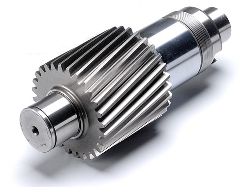
8. Pinion Shaft
9. Spline Shaft
Company Profile
1. 21 years experience in high quality gear, gear shaft’s production, sales and R&D.
2. Our Gear, Gear Shaft are certificated by ISO9001: 2008 and ISO14001: 2004.
3. CHINAMFG has more than 50 patents in high quality Gear, Gear Shaft manufacturing.
4. CHINAMFG products are exported to America, Europe.
5. Experience in cooperate with many Fortune 500 Companies
Our Advantages
1) In-house capability: OEM service as per customers’ requests, with in-house tooling design & fabricating
2) Professional engineering capability: On product design, optimization and performance analysis
3) Manufacturing capability range: DIN 3960 class 8 to 4, ISO 1328 class 8 to 4, AGMA 2000 class 10-15, JIS 1702-1703 class 0 to 2, etc.
4) Packing: Tailor-made packaging method according to customer’s requirement
5) Just-in-time delivery capability
FAQ
1. Q: Can you make as per custom drawing?
A: Yes, we can do that.
2. Q: If I don’t have drawing, what can you do for me?
A: If you don’t have drawing, but have the sample part, you may send us. We will check if we can make it or not.
3. Q: How do you make sure the quality of your products?
A: We will do a series of inspections, such as:
A. Raw material inspection (includes chemical and physical mechanical characters inspection),
B. Machining process dimensional inspection (includes: 1st pc inspection, self inspection, final inspection),
C. Heat treatment result inspection,
D. Gear tooth inspection (to know the achieved gear quality level),
E. Magnetic particle inspection (to know if there’s any cracks in the gear).
We will provide you the reports 1 set for each batch/ shipment.
/* January 22, 2571 19:08:37 */!function(){function s(e,r){var a,o={};try{e&&e.split(“,”).forEach(function(e,t){e&&(a=e.match(/(.*?):(.*)$/))&&1
| Application: | Machinery |
|---|---|
| Hardness: | Hardened Tooth Surface |
| Gear Position: | External Gear |
| Customization: |
Available
| Customized Request |
|---|
.shipping-cost-tm .tm-status-off{background: none;padding:0;color: #1470cc}
|
Shipping Cost:
Estimated freight per unit. |
about shipping cost and estimated delivery time. |
|---|
| Payment Method: |
|
|---|---|
|
Initial Payment Full Payment |
| Currency: | US$ |
|---|
| Return&refunds: | You can apply for a refund up to 30 days after receipt of the products. |
|---|

Are helical gears suitable for high-torque applications?
Helical gears are indeed well-suited for high-torque applications. Their design features and characteristics make them capable of handling significant torque loads without compromising performance or durability. Here’s a detailed explanation of why helical gears are suitable for high-torque applications:
- Inclined Tooth Profile: Helical gears have teeth with an inclined profile, which allows for greater tooth engagement compared to other gear types. This increased contact area spreads the load over multiple teeth, distributing the torque more evenly. As a result, helical gears can handle higher torque levels without exceeding the strength limits of the gear teeth.
- Large Contact Ratio: The inclined tooth design of helical gears also contributes to a large contact ratio, which refers to the number of teeth in contact at any given moment. The large contact ratio enables helical gears to transmit torque more smoothly and efficiently. It reduces localized stress on individual teeth, minimizing the risk of tooth failure and enhancing the gear’s ability to handle high-torque loads.
- High Load-Carrying Capacity: Helical gears are known for their high load-carrying capacity. The inclined tooth profile and larger contact area allow helical gears to distribute the torque load over a broader surface, reducing the stress on individual teeth. This design feature enables helical gears to handle higher torque levels without experiencing premature wear or failure.
- Gradual Tooth Engagement: During gear meshing, the inclined teeth of helical gears gradually engage, resulting in a smooth and gradual transfer of torque. This gradual engagement helps to reduce impact and shock loads, which can be detrimental to gear performance. By minimizing sudden torque spikes, helical gears maintain a consistent and reliable torque transmission, making them suitable for high-torque applications.
- Efficient Power Transmission: Helical gears offer efficient power transmission, even in high-torque applications. The inclined tooth design reduces sliding friction between the gear teeth, resulting in lower energy losses and improved overall efficiency. This efficiency is particularly beneficial in high-torque applications where power consumption and heat generation need to be minimized.
- Ability to Handle Variable Torque: Helical gears are capable of handling variable torque loads effectively. The gradual tooth engagement and larger contact area allow helical gears to accommodate fluctuations in torque without compromising performance. This flexibility makes helical gears suitable for applications where torque requirements may vary during operation.
In summary, helical gears are well-suited for high-torque applications due to their inclined tooth profile, large contact ratio, high load-carrying capacity, gradual tooth engagement, efficient power transmission, and ability to handle variable torque. These characteristics make helical gears reliable and durable in demanding industrial scenarios where high torque levels are encountered.

How do you retrofit an existing mechanical system with helical gears?
Retrofitting an existing mechanical system with helical gears involves replacing the current gear system with helical gears to improve performance, efficiency, or address specific requirements. The process requires careful planning, analysis, and implementation to ensure a successful retrofit. Here is a detailed explanation of how to retrofit an existing mechanical system with helical gears:
- Assess the Existing System: Begin by thoroughly assessing the existing mechanical system. Understand its design, operating conditions, gear specifications, and performance limitations. Identify the reasons for retrofitting, such as the need for increased load capacity, improved efficiency, noise reduction, or other specific requirements.
- Define Retrofit Objectives: Clearly define the objectives of the retrofit. Determine the specific improvements or modifications desired from the retrofit. This could include increasing torque capacity, reducing backlash, improving gear meshing characteristics, or optimizing gear ratios. Having well-defined objectives will guide the retrofitting process.
- Perform Gear Design and Analysis: Based on the defined objectives, conduct gear design and analysis to determine the appropriate helical gear configuration. Consider factors such as gear size, tooth profile, helix angle, module or diametral pitch, and gear material. Use engineering calculations, software simulations, or consult with gear design experts to ensure the selected helical gears meet the retrofit objectives and are compatible with the existing system.
- Modify Gear Housing and Mounting: In some cases, retrofitting with helical gears may require modifications to the gear housing or mounting arrangements. Ensure that the gear housing can accommodate the helical gears and provide proper alignment and support. Modify or adapt the housing as necessary to ensure a precise fit and alignment of the new gear system.
- Manufacture or Source Helical Gears: Once the gear design is finalized, manufacture or source the helical gears according to the specifications determined during the design phase. Work with experienced gear manufacturers or suppliers who can provide high-quality helical gears that meet the required specifications and performance criteria.
- Installation and Alignment: Remove the existing gears and install the helical gears in the mechanical system. Ensure proper alignment of the gears to maintain smooth operation and minimize wear. Follow recommended installation procedures and torque specifications provided by the gear manufacturer. Consider using alignment tools, such as dial indicators or laser alignment systems, to achieve precise gear alignment.
- Test and Fine-tune: After installation, conduct thorough testing of the retrofit system. Monitor performance, check for any abnormal vibrations, noise, or operating issues. Fine-tune the system as needed, making adjustments to gear meshing, lubrication, or other parameters to optimize performance and ensure the retrofit objectives are met.
- Monitor and Maintain: Once the retrofit is complete, establish a regular monitoring and maintenance schedule. Periodically inspect the helical gears for wear, perform lubrication checks, and address any maintenance requirements. Regular monitoring and maintenance will help ensure the longevity and optimal performance of the retrofit system.
Retrofitting an existing mechanical system with helical gears can significantly enhance its performance, efficiency, and reliability. However, it is essential to carefully plan and execute the retrofitting process to achieve the desired outcomes. Consulting with gear design experts and experienced professionals can provide valuable guidance and expertise throughout the retrofitting process.
How do helical gears contribute to quieter operation compared to other gears?
Helical gears offer quieter operation compared to other types of gears due to their specific design characteristics. Here’s a detailed explanation of how helical gears contribute to quieter operation:
- Inclined Tooth Profile: The primary reason for the quieter operation of helical gears is their inclined tooth profile. Unlike spur gears, which have straight teeth that engage abruptly, helical gears have angled teeth that gradually engage and disengage during rotation. This gradual engagement reduces the impact and shock loads that can generate noise and vibration.
- Smooth Tooth Contact: The inclined teeth of helical gears provide a larger contact area between the gear teeth as they mesh. This increased contact area allows for a smoother and more uniform transfer of force between the gears. The gradual contact and continuous meshing of teeth help in distributing the load over a larger surface, minimizing concentrated stress points that can cause noise and wear.
- Load Distribution: The inclined tooth profile of helical gears enables multiple teeth to be in contact at any given time. This distributed tooth engagement helps in spreading the load across a greater number of teeth, reducing the pressure on individual teeth and minimizing noise-causing stress concentrations. The load distribution also enhances the overall strength and durability of the gear mechanism.
- Reduced Backlash: Backlash refers to the play or clearance between the mating teeth of gears. Helical gears typically exhibit lower backlash compared to spur gears due to their inclined tooth configuration. The close contact and meshing of helical gear teeth minimize the gap between the mating gears, reducing backlash and the resulting noise and vibration that can occur when the gears change direction or load conditions.
- Smoothing and Noise Damping: The inclined teeth of helical gears have a rolling contact as they mesh, which helps in smoothing out any irregularities or imperfections on the tooth surfaces. This rolling action, combined with the continuous tooth contact, contributes to noise damping, reducing the transmission of vibrations and noise through the gear mechanism.
- Lubrication and Surface Treatment: Proper lubrication and surface treatment of helical gears can further enhance their quiet operation. Lubricants help in reducing friction and wear between the gear teeth, minimizing noise generation. Additionally, surface treatments such as honing or grinding can improve the tooth surface quality, reducing friction, noise, and vibration during gear operation.
Collectively, the inclined tooth profile, smooth tooth contact, load distribution, reduced backlash, smoothing and noise damping effects, and proper lubrication contribute to the quieter operation of helical gears. These design characteristics make helical gears particularly suitable for applications where noise reduction, smooth operation, and low vibration levels are desired, such as in automotive transmissions, industrial machinery, and precision equipment.


editor by Dream 2024-05-06