Tag Archives: gear reduction motor

China Precision Electric AC Gear Motor 3 Stage Single Speed Helical Transmission Reduction Gearbox helical gearbox arrangement

Merchandise Description

If you have any concern,you should speak to us, we will go all out to provide all the buyers with high quality and services.


/ Piece
|
1 Piece

(Min. Order)

###

Shipping Cost:

Estimated freight per unit.


To be negotiated|


Freight Cost Calculator

###

Application: Motor, Electric Cars, Motorcycle, Machinery, Marine, Toy, Agricultural Machinery, Car
Hardness: Hardened Tooth Surface
Installation: Vertical Type

###

Samples:
US$ 8.2/Piece
1 Piece(Min.Order)

|

Order Sample

###

Customization:
Available

|


How to Choose a Helical Gearbox

Choosing the best helical gearbox is dependent on the type of application you want to use the gear for. You will need to consider the contact ratios and the total of profile shifts required.helical gearbox

Spur gears are more efficient than helical gears

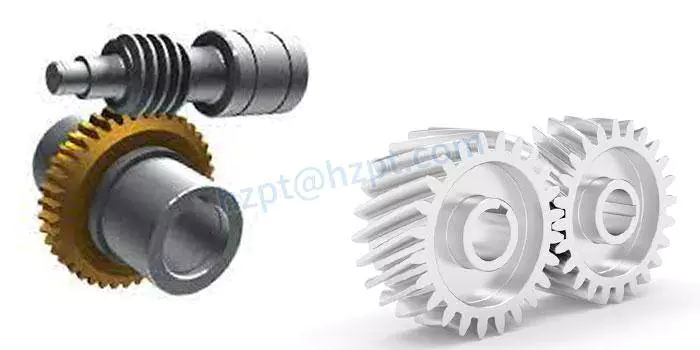
Compared to helical gears, spur gears have straight teeth that are parallel to the axis of the gear. Because they are more efficient, spur gears are often used in low speed applications. However, helical gears are better for low-noise and high-speed applications. Despite their advantages, spur gears are also used in some devices.
Spur gears are not as resilient as other gears. They are less efficient at transmitting power over long distances, and they generate too much noise at high speeds. They also impose a radial load on bearings. They also produce significant vibration that can limit the maximum speed of operation.
Helical gears are better at transferring loads. They are used in a number of applications, including car transmissions, elevators, and conveyors. Helical gears also generate large amounts of thrust. They are also quieter than spur gears.
Unlike spur gears, helical gears use bearings to support their thrust load. They also have more teeth, so they can handle more load than spur gears. They can also be used in non-parallel shafts.
Helical gears are generally used in high-speed mechanical systems. They also have less wear on individual teeth and are quieter running than spur gears.
Helical gears are a refinement of spur gears. They are also used in the printing industry, elevators, and gearboxes for automobiles. They are often used in conjunction with a worm gear to distribute load. They have a higher speed capacity, but they are not as efficient as spur gears. They are used in some high-speed mechanical systems because they generate less noise and vibration.
Spur gears are commonly used in low-speed applications, like rack and pinion setups. Their design makes them more efficient at transmitting power, but they are less resilient than helical gears.
Design space is limited based on a required center distance, target gear ratio, and sum of profile shifts
Using statistically derived parameters, the authors performed a multi-objective optimization of the profile shift of two external cylindrical gears. The main objective of this study was to maximize efficiency and minimize the amount of power lost in the optimized space.
To do this, the authors used a multi-objective optimization algorithm that included all aspects of the optimal profile shift. The algorithm evaluates objective function over a series of generations to determine the best solution.
The multi-objective optimization algorithm was based on a verified optimization algorithm. This algorithm combines analytical pressure loads estimation with an effective method for calculating the deformations of the gear case. Using the aforementioned formulae, the authors were able to identify a feasible solution. The numerical calculations also showed that the corresponding specific sliding coefficients were perfectly balanced.
To identify the most efficient method for determining the profile shift, the authors selected the most efficient method based on the objectives of efficiency and mass. The efficiency objective was considered to be the largest given the small size of the resulting optimization space. This objective is useful in reducing wear failures.
helical gearbox
The largest thermal treatment of a cylindrical gear is case hardening. The ISO/TR 4467:1982 standard provides a practical guide for gears. The largest radii of the pinion and wheel are rb1 and rb2. The ratio of tooth width to base circle diameter of the pinion is normally set to less than 1.
Sliding velocity increases as the distance from the pitch point increases in the line of action
Deflections of the involute profile of a helical gear occur due to the load on the teeth. However, the optimum pressure angle for the gear is not known.
The correct pressure angle for a helical gear cannot be calculated without a surface model. Assuming the pressure is uniform over the profile, a pressure angle of 20deg would be a good bet. However, this would require a mathematical model that can be derived from the Archard wear equation.
In general, the pressure angle will be influenced by the diameter, as well as the gear mesh geometry. It is important to know the actual angle of a helical gear since this will affect the curvature of the profile, the normal force, and the radial force.
The best way to measure the pressure angle is to consider the theoretical pitch diameter. If the pitch diameter is small, then the actual angle will be smaller. This will cause a gap between the flanks. However, it can also cause the gear to deform, leading to unexpected working behavior.
One interesting tangent is the pitch plane, an imaginary plane tangent to the pitch surfaces. The pitch plane is the plane perpendicular to the axial plane of the gear cross section. It is usually used as a reference point to calculate the transverse pressure angle.
The working pressure angle is the angle of the pressure line of the gear mesh. This angle is the same as the reference pressure angle, but the length of the contact line is reduced.
The best way to calculate the working pressure angle is to use the pressure line of the gear mesh. This will give a more accurate value. The actual angle of the pressure line is also related to the transmission ratio. This ratio is usually given as the nominal ratio of angular velocities. The actual velocities will fluctuate about this ratio.

Undercut of a helical gear tooth root

Having an undercut at the pinion root can affect the distribution of load along the line of contact of helical gears. This can result in higher than nominal loads on some teeth and amplitude modulated noise.
The tooth root is affected by a number of factors, including the shape of the tooth cutting tool. The cutting tool must be designed to avoid an undercut without reducing the number of teeth. This is achieved by a process called profile shifting.
Profile shift occurs when the cutting tool changes depth, thereby preventing an undercut. It is often used in the manufacturing process to achieve a greater overlap ratio. The higher the overlap ratio, the less variation there is between the contact lines. This reduces the dynamic tooth loads and reduces noise.
The profile shift is most often associated with the cutting tool tip. This is the point where the involute profile exits the gear, before the tip begins to taper. The involute profile can be defined for every transverse section of the gear face width. The boundary point is a point of tangency between the involute and root profiles.
The involute of a circle is a common way to define a gear-tooth profile. The involute is the path traced by the point on the line when rolling on a circle. It is a useful feature for cylindrical involute gears.
The helix angle is also important to the helical gear. It allows for greater contact capacity and increases the bending capacity of the gear. It must be included in specifications for helical teeth. The angle must be measurable and include the (+-) sign.
The bending strength of a tooth depends on the shape of the root. A large undercut reduces the strength of the tooth.helical gearbox

Contact ratios

Whether a helical gearbox is dynamic or steady-state, the contact ratio is a key factor. The total contact ratio defines the average number of teeth in contact in the plane of action. It is calculated by multiplying the transverse contact ratio with the overlap ratio. The overlap ratio is always non-zero.
The total contact ratio must be 1.0 or greater for a constant speed rotation on the driven side. Gears with a low total contact ratio are known to slow down rotation of the driven gear. The total contact ratio is influenced by the length of the contact line. A high contact ratio is a good choice for dynamic loading.
A low contact ratio results in a greater amount of profile shift and a larger amount of noise. If the contact ratio is too high, it may cause excessive EAP sliding velocity and cause scuffing. In addition, an uneven load share results in amplitude modulated vibrations.
A helical gear is a pair of slim spur gears. The gears are layered in a plane that runs parallel to the face width of the gear teeth. Each gear tooth makes contact with the flank of the next gear tooth. The helical gear tooth flank is a 3-dimensional surface that is a tangent to the base circles of the gears.
The tooth shape of the helical gear tooth is also a key factor in the contact ratio. The tooth form is designed to be in relation to the work piece, tooling, dedendum coefficients, tooth forces, and tooth bending stiffness. A gear tooth form must also relate to tooth surface kinematics and microgeometry modifications.
The active profile is a region of the involute profile between the start and end points. A tooth profile that satisfies the basic law of gear-tooth action is often called a conjugate profile.
China Precision Electric AC Gear Motor 3 Stage Single Speed Helical Transmission Reduction Gearbox     helical gearbox arrangementChina Precision Electric AC Gear Motor 3 Stage Single Speed Helical Transmission Reduction Gearbox     helical gearbox arrangement
editor by czh 2023-03-24

China RF Series Low Rpm Reducer Gearbox High Torque AC Motor Helical Gear Box double reduction helical gearbox

Item Description

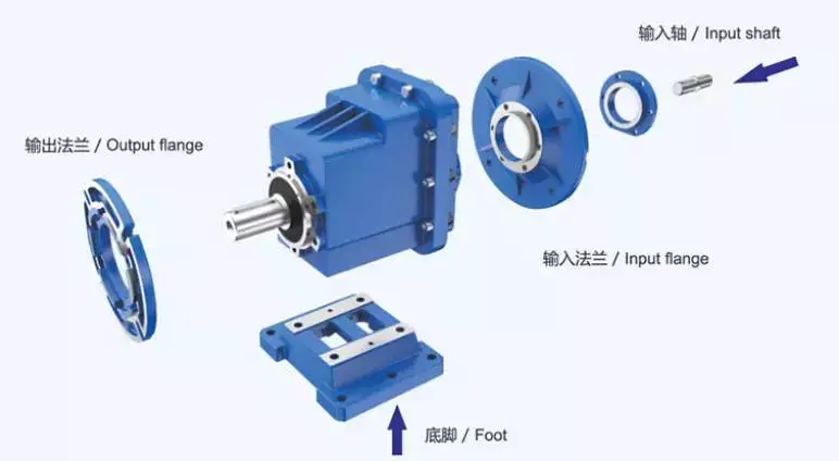
Helical Gear Motor (R Kind) 

Enter Configurations

Motor mounted
IEC B5/B14 Motor Flange (AM Flange)
Servo Motor Flange (AQA Flange)
Shaft Enter (Advert relationship)

Output Configurations

Reliable output shaft

Solid output shaft with flange

Variants of Helical Gear Device Collection RX / R / RF

Single Stage or 2/3 Stage

Foot- or flange-mounted

Foot- and flange-mounted

Flange-mounted with extended bearing housing

Main Feature
R type gear reducer is an best choice for substantial output speeds or reduced fat. Usually with a high stage of performance, our helical equipment models offer you an the best possible ratio in between output torque and set up space. This indicates: a helical equipment device nearly always matches your software.
Specification

Product

Sound Output Shaft Dia./Length

mm

Horizontal Center Peak mm

Exterior Flange Dia.

 mm

Power

(kw)

Ratio

(i)

Nominal Torque

(Nm)


R/RF37

ф25/fifty

90

a hundred and twenty

.twelve-.seventy five

5-136

a hundred and fifty

R/RF47

ф30/sixty

a hundred and fifteen

160

.twenty five-2.2

five-173

300


R/RF57

ф35/70

one hundred fifteen

200

one.eighteen-5.five

five-173

400


R/RF67

ф35/70

one hundred thirty

200

.37-7.5

5-170

500


R/RF77

ф40/80

140

250

.55-11.

5-192

750


R/RF87

ф50/a hundred

a hundred and eighty

three hundred

.75-18.five

5-192

1250


R/RF97

ф60/one hundred twenty

225

350

1.50-thirty.

5-197

2400


R/RF107

ф70/a hundred and forty

250

350

2.twenty-forty five.

five-197

3600


R/RF137

ф90/a hundred and seventy

315

450

four.00-forty five.00

five-197

6600


R/RF147

ф110/210

355

450

seven.50-90.00

5-195

10700


R/RF167

ф120/210

425

550

11.00-132.00

5-186

14800


Organization Profile
Packing
Scenarioes

FAQ
Q1: I want to get your merchandise, how can I shell out?
A: You can shell out by means of T/T(30%+70%), L/C ,D/P and so forth. 

Q2: How can you guarantee the high quality?
A: One particular year’s warranty in opposition to B/L day. If you satisfy with top quality problem, please send out us photos or movie to verify, we promise to send spare areas or new products to change. Our promise not incorporate inappropriate procedure or wrong specification assortment. 

Q3: How we pick versions and technical specs?
A: You can e mail us the collection code (for illustration: RC series helical gearbox) as effectively as necessity particulars, this kind of as motor electrical power,output speed or ratio, provider aspect or your application…as a lot information as attainable. If you can provide some pictures or drawings,it is good. 

This autumn: If we don’t discover what we want on your internet site, what ought to we do?
A: We offer you 3 options:
1, You can e-mail us the pictures, drawings or descriptions particulars. We will attempt to layout your items on the basis of our
common models.
2, Our R&D division is expert for OEM/ODM merchandise by drawing/samples, you can send out us samples, we do tailored style for your bulk purchasing.
three, We can produce new merchandise if they have good marketplace. We have currently created numerous things for unique employing effective, these kinds of as special gearbox for agitator, cement conveyor, shoes machines and so on. 

Q5: Can we get 1 laptop of every merchandise for high quality tests?
A: Yes, we are happy to acknowledge trial get for top quality screening.

Q6: How about your solution delivery time?
A: Generally for 20’container, it will take twenty five-30 workdays for RV series worm gearbox, 35-40 workdays for helical gearmotors.

US $80-200
/ Piece
|
5 Pieces

(Min. Order)

###

Application: Motor, Machinery, Agricultural Machinery
Hardness: Hardened Tooth Surface
Installation: Foot/Flange Mounted
Layout: Coaxial
Gear Shape: Cylindrical Gear
Step: Single-Step

###

Customization:

###

Input Configurations
Motor mounted
IEC B5/B14 Motor Flange (AM Flange)
Servo Motor Flange (AQA Flange)
Shaft Input (AD connection)
Output Configurations
Solid output shaft
Solid output shaft with flange
Variants of Helical Gear Unit Series RX / R / RF
Single Stage or 2/3 Stage
Foot- or flange-mounted
Foot- and flange-mounted
Flange-mounted with extended bearing housing

###

Model
Solid Output Shaft Dia./Length
mm
Horizontal Center Height mm
External Flange Dia.
 mm
Power
(kw)
Ratio
(i)
Nominal Torque
(Nm)
 
R/RF37
ф25/50
90
120
0.12-0.75
5-136
150
R/RF47
ф30/60
115
160
0.25-2.2
5-173
300
 
R/RF57
ф35/70
115
200
1.18-5.5
5-173
400
 
R/RF67
ф35/70
130
200
0.37-7.5
5-170
500
 
R/RF77
ф40/80
140
250
0.55-11.0
5-192
750
 
R/RF87
ф50/100
180
300
0.75-18.5
5-192
1250
 
R/RF97
ф60/120
225
350
1.50-30.0
5-197
2400
 
R/RF107
ф70/140
250
350
2.20-45.0
5-197
3600
 
R/RF137
ф90/170
315
450
4.00-45.00
5-197
6600
 
R/RF147
ф110/210
355
450
7.50-90.00
5-195
10700
 
R/RF167
ф120/210
425
550
11.00-132.00
5-186
14800
 

Helical Gearbox

Using a helical gearbox can greatly improve the accuracy of a machine and reduce the effects of vibration and shaft axis impact. A gearbox is a circular machine part that has teeth that mesh with other teeth. The teeth are cut or inserted and are designed to transmit speed and torque.helical gearbox

Sliding

Among the many types of gearboxes, the helical gearbox is the most commonly used gearbox. This is because the helical gearbox has a sliding contact. The contact between two gear teeth begins at the beginning of one tooth and progresses to line contact as the gear rotates.
Helical gears are cylindrical gears with teeth cut at an angle to the axis. This angle enables helical gears to capture the velocity reversal at the pitch line due to the sliding friction. This leads to a much smoother motion and less wear. Moreover, the helical gearbox is more durable and quieter than other gearboxes.
Helical gears are divided into two categories. The first group comprises of crossed-axis helical gears, commonly used in automobile engine distributor/oil pump shafts. The second group comprises of zero-helix-angle gears, which do not produce axial forces. However, they do create heat, which causes loss of efficiency.
The helical gearbox configuration is often confounded, which results in higher working costs. In addition, the helical gearbox configuration does not have the same torque/$ ratio as zero-helix angle planetary gears.
When designing gears, it is important to consider the effects of gear sliding. Sliding can lead to friction, which can cause loss of power transmission. It also leads to uneven load distribution, which decreases the loadability of the helical planetary gearbox.
In addition, the mesh stiffness of helical gears is commonly ignored by researchers. An analytical model for the mesh stiffness of helical gears has been proposed.

Axial thrust forces

Several options are available for axial thrust forces in helical gearboxes. The most obvious is to use a double helical gear to offset the force component. Another option is to use a thrust bearing with a lower load carrying capacity. This becomes a sacrificial component.
In order to transmit a force, it must be distributed along the contact line. This force is the sum of tangential, radial and axial force components. All these components must be transferred from the source to the output. This is a complex process that involves the use of gears.
The axial force component must be transferred through the gears. The resultant force is then divided into orthogonal components and divided into the thrust directions. The radial force component is from the contact point to the driven gear center.
The axial force component is also determined by the size of the gear’s pitch diameter. A larger pitch diameter results in a greater bearing moment. Similarly, a larger gear ratio will produce a higher torque transmission.
It should be noted that the axial force component is only a small part of the total force. The normal force is distributed along the contact line.
The double helical gear is also not a perfect duplicate of the herringbone gear. It has two equal halves. It is used interchangeably with the herringbone gear. It also has the same helix angle.helical gearbox

Reduced impact on the shaft axis

Increasing the helix angle of a gear pair will reduce resonance effects on the shaft axis of a helical gearbox. However, this will not reduce the overall vibration in the gearbox. In fact, it will increase the vibration. This can lead to serious fatigue faults in the drive train.
This is because the helix angle has an effect on the contact line between two teeth. As the helix angle increases, the length of the contact line decreases. In addition, it has an effect on the normal force and curvature radii of the teeth. The pressure angle also affects the curvature radii.
Helical gears have several advantages over spur gears. These advantages include: lower vibration, NVH (noise, vibration and harshness) characteristics, and smooth operation under heavy loads. They also have better torque capability. However, they produce higher friction. They also require unique approaches to control their thrust forces.
The first step in reducing resonance effects is to regulate the meshing frequency of the helical gear stage. This can be done by varying the shift factors in the gear. If the shift factors are too large, then the gear will experience resonance effects. The helix angle is also affected by the gear’s shift factors. It is therefore important to control the gear’s geometry in order to reduce the resonance effects.
Next, the effects of the web structure and rim thickness on the root stress of the gear are examined. These are measured by strain gage. The results indicate that the maximum root stress is obtained when the worst meshing position is reached.

Quieter operation

Compared to spur gears, helical gears are much quieter in operation. This is due to their larger teeth. Aside from this, they have a higher load-carrying capacity. They also run smoother and have a higher speed capability. Helical gears are also a good substitute for spur gears.
The most significant parameter relating to noise reduction is the gear contact ratio. It ranges from below 1 to more than 10 and is determined by the number of teeth intersecting a parallel shaft line at the pith circle. It is also a good indicator of the level of noise reduction that helical gears provide.
In addition, helical gears have a lower impulse flexure than spur gears. This is because the contact point slides along the helical surface of each tooth. This also adds internal damping to the gear system.
While helical gears are less noisy than spur gears, they do have a high level of wear and tear. This can affect the performance of the gear. However, it is possible to improve the smoothness of the tooth surface by grinding. In addition, running the gears in oil can also help improve the smoothness of the tooth surface.
There are many industries that use helical gears. For example, the automotive industry uses them in their transmissions. They also are used in the agricultural industry. They are often used in heavy trucks.
Helical gears are also known to generate less heat and are quieter than other gears. They can also deliver parallel power transfers between parallel or non-parallel shafts.

Improved accuracy

Increasing the accuracy of a helical gearbox is the key to its operation and reliability. The accuracy of the gearbox is dependent on several features. Among the most important are the profile and lead. Moreover, the power requirements of a gear drive should be taken into consideration.
The profile is the most sensitive feature of a helical gear. If the profile is not symmetric, the gear will run with a noisy spur gear. In addition, the profile is also the most sensitive to lead.
A helical gearbox plays a key role in the power transmission of industrial applications. However, the heavy duty operating conditions make it susceptible to a variety of faults.
A helical gearbox’s performance depends on the accuracy of the individual gears. This is accomplished by minimizing the backlash. A common way to reduce backlash is to approach all target positions from a common direction. This approach also reduces transmission noise.
The accuracy of a helical gearbox can be improved by using a flexible electronic gearbox. This can reduce the degree of twist. Moreover, it can increase the accuracy of gear machining.
A helical gearbox with an electronic gearbox can increase the accuracy of twist compensation. It can also improve the linkage between B-axis, C-axis, and Z-axis. Moreover, the electronic gearbox will ensure the linkage relationship between Y-axis, Z-axis, and C-axis.
The accuracy of a helical Gearbox can be improved by calculating the position error of the gear train. Pitch deviation and helix angle deviation are two types of position error.helical gearbox

Reduced vibration

Using helical gearboxes can reduce vibration and noise. These gears are used in a variety of applications, including automotive transmissions. Moreover, these gears are quiet enough to operate in noise-sensitive applications.
Using CZPT software, three different gearbox housing designs are compared. The external dimensions and mass of each design are kept constant, but different quantities of longitudinal and transverse stiffeners are employed. The resulting models are then compared to experimental results. In addition, the free vibration response of these models is analyzed. The results are shown in Fig. 5.
In terms of noise reduction, the cellular model produces the lowest sound pressure level. However, the cross model produces the higher sound level. The cellular model also produces better peak to peak results.
The input-stage gear pair is the power source of the output-stage gear pair. The output-stage gear pair’s vibration is also studied. This includes a phase diagram and a frequency-domain diagram. The influence of the driving torque and the pinion’s velocity on the vibration is studied in a numerical manner. The time evolution of the normal force and the lubricant stiffness is also studied.
The input-stage pinion modification reduces the input-stage gear pair’s vibration. This reduction is achieved by adding dual bearing support to the input shaft.
China RF Series Low Rpm Reducer Gearbox High Torque AC Motor Helical Gear Box     double reduction helical gearboxChina RF Series Low Rpm Reducer Gearbox High Torque AC Motor Helical Gear Box     double reduction helical gearbox
editor by czh 2023-01-22

China Trc Inline Helical Gear Transmission Gearbox for IEC Motor double reduction helical gearbox

Solution Description

Item Description

KPC Series helical gearbox is a new era item which designed basing on the modular program, It can be connected respectively with motors this kind of as IEC normal motor, brake motor, explosion-proof motor, frequency motor, servo motor and so on. it has 4 types(),electricity from .12kw to 4.0kw, ratio from 3.sixty six to fifty eight.09, Max torque from 120Nm to 500Nm.It can be link discretionary(foot or flange) and use multi-mounting positions appropriately. This merchandise is broadly used in textile, foodstuff, beverage,tobacco, logistics industrial fields,and so forth.

        Solution Attributes

  1. Modular construction
  2. Higher performance
  3. Specific grinding, low sound
  4. Compact structural style
  5. Univeral mounting
  6. Aluminium housing, mild in bodyweight
  7. Carbonize and grinding hardened gears, durable
  8. Multi-framework, can be merged in different forms to satisfy different transmission situation

       Installation:
      1.Foot mounted
      2.Output Flange mounted
      3.B14 Flange mounted

      Designs:
      1.KPC..P(Foot-mounted): KPC01P,KPC02P,KPC03P,KPC04P
      2.KPCF..P(Output Flange-mounted): KPCF01P,KPCF02P,KPCF03P,KPCF04P
      3.KPCZ..P(B14 Flange-mounted): KPCZ01P,KPCZ02P,KPCZ03P,KPCZ04P

Comprehensive Photos

Product Parameters

GEARBOX Choosing TABLES  
KPC01..       n1=1400r/min       120Nm  
n2 M2max Fr2 i Proportion 63B5 71B5/B14 80B5/B14 90B5/B14  
[r/min] [Nm] [N]  
26 120 2600 53.33  a hundred and sixty/three          
31 one hundred twenty 2600 45.89  413/nine          
35 120 2600 forty.10  3248/eighty one          
39 one hundred twenty 2560 35.47  532/fifteen          
forty nine 120 2380 28.50  770/27          
fifty nine a hundred and twenty 2230 23.56  212/9          
71 one hundred twenty 2100 19.83  119/six          
seventy eight 90 2030 17.86  1357/76          
ninety six 120 1900 14.62  658/45          
a hundred and one 90 1860 13.80* 69/five          
118 120 1770 11.90  2464/207          
143 a hundred and twenty 1660 nine.81  1148/117          
153 80 1630 nine.17  1219/133          
181 eighty 1540 seven.72  1173/152          
246 70 1390 five.69  1081/one hundred ninety          
302 70 1290 four.63  88/19          
366 70 1210 3.82  943/247          
KPC02..       n1=1400r/min       200Nm  
n2 M2max Fr2 i Proportion 63B5 71B5/B14 80B5/B14 90B5/B14  
[r/min] [Nm] [N]  
26 two hundred 4500 fifty four.00* 54/1          
thirty 200 4500 46.forty six* 3717/80          
34 two hundred 4500 40.60* 203/5          
39 two hundred 4270 35.ninety one* 3591/a hundred          
48 two hundred 3970 28.88* 231/8          
fifty nine 200 3730 23.85* 477/twenty          
70 200 3520 20.08* 3213/160          
82 140 3330 seventeen.10  3009/176          
ninety five two hundred 3180 14.81* 2961/two hundred          
106 140 3060 13.21  2907/220          
116 two hundred 2970 12.05  1386/one hundred fifteen          
141 200 2780 9.93  2583/260          
159 a hundred and twenty 2670 eight.78  2703/308          
189 a hundred and twenty 2520 seven.39  2601/352          
257 100 2280 5.45  2397/440          
316 one hundred 2120 4.43  102/23          
383 eighty 1990 3.66  2091/572          
KPC03..       n1=1400r/min         300Nm
n2 M2max Fr2 i Proportion 71B5/B14 80B5/B14 90B5/B14 100B5/B14 112B5/B14
[r/min] [Nm] [N]
24 300 6000 58.09  639/eleven          
28 three hundred 6000 50.02  2201/forty four          
32 300 6000 43.75  4331/99          
36 three hundred 6000 38.73  426/eleven          
40 300 5860 34.62  4189/121          
forty nine 300 5480 28.30  4047/143          
sixty four 280 5571 21.78  1917/88          
eighty one 280 4660 seventeen.33  3621/209          
ninety three 260 4440 fifteen.06  497/33          
113 260 4160 12.37  1633/132          
136 240 3910 10.28  3053/297          
177 180 3590 7.93  1269/160          
222 a hundred and eighty 3320 six.31  2397/380          
255 one hundred fifty 3170 5.48  329/sixty          
311 150 2970 4.50  1081/240          
374 a hundred and fifty 2790 three.74  2571/540          
KPC04..       n1=1400r/min       500Nm  
n2 M2max Fr2 i Proportion 80B5/B14 90B5/B14 100B5/B14 112B5/B14  
[r/min] [Nm] [N]
24 five hundred 8000 fifty eight.09  639/11          
28 five hundred 8000 50.02  2201/44          
32 five hundred 8000 forty three.75  4331/99          
36 500 8000 38.73  426/eleven          
40 500 7950 34.62  4189/121          
49 500 7430 28.30  4047/143          
64 480 6810 21.78  1917/88          
81 480 6310 17.33  3621/209          
ninety three 460 6571 fifteen.06  497/33          
113 460 5640 twelve.37  1633/132          
136 440 5300 10.28  3053/297          
177 260 4860 seven.93  1269/160          
222 260 4510 6.31  2397/380          
255 230 4300 five.48  329/sixty          
311 230 4030 four.50  1081/240          
374 two hundred 3780 three.74 2571/540          

Outline Dimension:

Company Profile

About our organization:
We are a professional reducer maker positioned in HangZhou, ZHangZhoug province.Our top goods is  full selection of RV571-one hundred fifty worm reducers , also supplied hypoid helical gearbox, Personal computer units, UDL Variators and AC Motors.Goods are broadly utilized for purposes this sort of as: foodstuffs, ceramics, packing, chemicals, pharmacy, plastics, paper-making, design machinery, metallurgic mine, environmental security engineering, and all sorts of automatic strains, and assembly strains.With fast shipping and delivery, superior right after-revenue provider, innovative producing facility, our goods offer well  both at home and abroad. We have exported our reducers to Southeast Asia, Eastern Europe and Middle East and so on.Our goal is to create and innovate on foundation of higher high quality, and produce a good popularity for reducers.

Packing data:Plastic Bags+Cartons+Wood Circumstances , or on request
We take part Germany Hannver Exhibition-ZheJiang PTC Fair-Turkey Acquire Eurasia

Logistics

We can dispatch goods by sea, by prepare, by air in accordance to customer instruction

Soon after Product sales Provider

one.Routine maintenance Time and Warranty:Within 1 12 months soon after receiving products.
2.Other ServicesLike modeling selection information, installation guide, and problem resolution guidebook, etc.

FAQ

one.Q:Can you make as for every customer drawing?
A: Sure, we offer tailored provider for consumers appropriately. We can use customer’s nameplate for gearboxes.

two.Q:What is your terms of payment ?
   A: thirty% deposit before production,equilibrium T/T just before shipping and delivery.

three.Q:Are you a trading organization or company?
   A:We are a manufacurer with advanced equipment and skilled workers.

four.Q:What is your manufacturing ability?
   A:8000-9000 PCS/Thirty day period

five.Q:Free of charge sample is available or not?
   A:Indeed, we can source free of charge sample if client agree to pay out for the courier cost

six.Q:Do you have any certificate?
   A:Of course, we have CE certificate and SGS certification report.

Get in touch with information:
Ms Lingel Pan
For any inquiries just truly feel free ton contact me. Many many thanks for your kind interest to our firm!

US $45-80
/ Piece
|
1 Piece

(Min. Order)

###

Application: Motor, Machinery, Marine, Agricultural Machinery, Industry
Function: Distribution Power, Change Drive Torque, Change Drive Direction, Speed Changing, Speed Reduction
Layout: Coaxial
Hardness: Hardened Tooth Surface
Installation: Horizontal Type
Step: Double-Step

###

Samples:
US$ 45/Piece
1 Piece(Min.Order)

|
Request Sample

###

Customization:

###

GEARBOX SELECTING TABLES  
KPC01..       n1=1400r/min       120Nm  
n2 M2max Fr2 i Proportion 63B5 71B5/B14 80B5/B14 90B5/B14  
[r/min] [Nm] [N]  
26 120 2600 53.33  160/3          
31 120 2600 45.89  413/9          
35 120 2600 40.10  3248/81          
39 120 2560 35.47  532/15          
49 120 2380 28.50  770/27          
59 120 2230 23.56  212/9          
71 120 2100 19.83  119/6          
78 90 2030 17.86  1357/76          
96 120 1900 14.62  658/45          
101 90 1860 13.80* 69/5          
118 120 1770 11.90  2464/207          
143 120 1660 9.81  1148/117          
153 80 1630 9.17  1219/133          
181 80 1540 7.72  1173/152          
246 70 1390 5.69  1081/190          
302 70 1290 4.63  88/19          
366 70 1210 3.82  943/247          
KPC02..       n1=1400r/min       200Nm  
n2 M2max Fr2 i Proportion 63B5 71B5/B14 80B5/B14 90B5/B14  
[r/min] [Nm] [N]  
26 200 4500 54.00* 54/1          
30 200 4500 46.46* 3717/80          
34 200 4500 40.60* 203/5          
39 200 4270 35.91* 3591/100          
48 200 3970 28.88* 231/8          
59 200 3730 23.85* 477/20          
70 200 3520 20.08* 3213/160          
82 140 3330 17.10  3009/176          
95 200 3180 14.81* 2961/200          
106 140 3060 13.21  2907/220          
116 200 2970 12.05  1386/115          
141 200 2780 9.93  2583/260          
159 120 2670 8.78  2703/308          
189 120 2520 7.39  2601/352          
257 100 2280 5.45  2397/440          
316 100 2120 4.43  102/23          
383 80 1990 3.66  2091/572          
KPC03..       n1=1400r/min         300Nm
n2 M2max Fr2 i Proportion 71B5/B14 80B5/B14 90B5/B14 100B5/B14 112B5/B14
[r/min] [Nm] [N]
24 300 6000 58.09  639/11          
28 300 6000 50.02  2201/44          
32 300 6000 43.75  4331/99          
36 300 6000 38.73  426/11          
40 300 5860 34.62  4189/121          
49 300 5480 28.30  4047/143          
64 280 5020 21.78  1917/88          
81 280 4660 17.33  3621/209          
93 260 4440 15.06  497/33          
113 260 4160 12.37  1633/132          
136 240 3910 10.28  3053/297          
177 180 3590 7.93  1269/160          
222 180 3320 6.31  2397/380          
255 150 3170 5.48  329/60          
311 150 2970 4.50  1081/240          
374 150 2790 3.74  2021/540          
KPC04..       n1=1400r/min       500Nm  
n2 M2max Fr2 i Proportion 80B5/B14 90B5/B14 100B5/B14 112B5/B14  
[r/min] [Nm] [N]
24 500 8000 58.09  639/11          
28 500 8000 50.02  2201/44          
32 500 8000 43.75  4331/99          
36 500 8000 38.73  426/11          
40 500 7950 34.62  4189/121          
49 500 7430 28.30  4047/143          
64 480 6810 21.78  1917/88          
81 480 6310 17.33  3621/209          
93 460 6020 15.06  497/33          
113 460 5640 12.37  1633/132          
136 440 5300 10.28  3053/297          
177 260 4860 7.93  1269/160          
222 260 4510 6.31  2397/380          
255 230 4300 5.48  329/60          
311 230 4030 4.50  1081/240          
374 200 3780 3.74 2021/540          

Why Choose a Helical Gearbox?

Choosing a helical gearbox is an important decision for any machine builder. It can help you to reduce maintenance costs, improve productivity and efficiency, and ensure that your equipment operates quietly and efficiently. In addition, it can also be compact in size and easy to install.helical gearbox

High productivity and efficiency

Compared to spur gears, helical gears have high productivity and efficiency. This is due to the fact that the helical gearbox is more effective at transferring power between right-angle configurations. Helical gears are also quieter. They also have the ability to tolerate a greater load. These gears are usually used in high-load applications, such as automotive transmission applications.
The basic features of helical gears include a slanted tooth face, a larger contact ratio, and a smoother performance. Helical gears are also less expensive than spur gears. They have more power carrying capacity, longer life, and are easier to maintain.
There are many factors that affect the efficiency of helical gearboxes. Some of them include the number of stages, reduction ratio, ambient conditions, and lubrication. They are also affected by the number of teeth.
Power loss in helical gears is mainly due to friction and heat. There are various approaches to minimize these losses. One approach is to analyse power losses using a numerical method.
Other factors that affect the efficiency of helical systems include speed, noise, and the number of teeth. The amount of power lost in gear mating is dependent on the load.

Low power consumption

Compared to other types of gearboxes, helical gearboxes have low power consumption. This is because they can tolerate more load, conduct smooth performance, and are quieter. They also require less oil changes and have a longer life span.
Helical gears have special teeth that are cut at an angle. The teeth are designed to engage gradually, rather than quickly. They can transfer power between parallel configurations and right-angle configurations.
Helical gearboxes are the most widely used gearboxes. They are also the most efficient. They can work at 98% efficiency. However, they are more expensive than spur gears. They can be packaged with oil-filled housings. They have less noise and require less maintenance. They can operate cooler, and have more torque capacity.
Helical gearboxes have two types: single and double helical gears. In the single type, the gears are perpendicular to the axis. They are usually used in automotive transmission applications. They can also be used in forward velocities. In the double type, the helical faces are next to each other.
Helical gears work at higher ratios, which increases their efficiency. They are also less noisy than spur gears. They are a good choice for applications that require high torque capacity. The basic efficiency of helical gearboxes ranges from 90% to 99.5%. They are also easier to operate and have a longer life span. They are suited to a wide range of applications.helical gearbox

Compact in size

Having a shiny new set of wheels is a nice change of pace. You get to sit in style and you get to drive it like the pro. The trick is finding the right one at the right time. Fortunately, there are plenty of companies who know how to build a high quality car that can be afforded by the average Joe. You’ll find all types of cars from sports coupes to hatchbacks. You’ll also find all types of drivers from the young professional to the seasoned veteran. You’ll also find all types of roads from main streets to back roads. There are even all types of parking spaces to choose from. With a bit of planning and some research, you’ll find the perfect fit for you and your family. You can’t help but wonder why you didn’t choose a vehicle with this many perks sooner. It’s a nice way to spend a night on the town, without having to worry about a parking fee. The next time you’re in the mood to take the family out to the country for a weekend in the great bluffs, you’ll know which ones to avoid.

Noise-free operation

Compared to spur gears, helical gears have better speed capability and quieter operation. However, helical gearboxes often have problems that stop their service. These faults result in increased productivity costs. These problems include fatigue, chipping tip, crack and missing tooth.
In this paper, we propose a novel signal processing scheme to detect gearbox faults at constant speed. The method involves the use of spectral subtraction (SS) to remove the spectral noise of a signal. This approach is widely used in speech signal processing. It is also used to estimate real-time noise information. The method was successfully applied to the analysis of gearbox faults.
The spectral subtraction technique is applied to the transmission error and to the side-band frequency feature. The side-band frequency is equal to the rotation frequency of the input shaft. A square envelope spectrum method is used to obtain the spectral feature. It was then used to obtain the corresponding fault signal. The method is then compared with experimentally measured noise data.
It is also important to note that the side-band feature is not stable in different noise levels. The optimal demodulation subband selection method is not obvious. However, the proposed method can obtain a stable amplitude value when SNR is low.
Another important factor that reduces noise is the overlap ratio. The overlap ratio is the sum of the transverse contact ratio and the face contact ratio. When the overlap ratio approaches one, the noise is minimized.

Improved performance at high speeds

Whether used in an industrial, automotive or power generation application, helical gearboxes provide a number of benefits over traditional spur gearing systems. These advantages include reduced noise, higher load capacity and smoother operation.
In an effort to reduce noise and improve performance at high speeds, Parker engineers developed a helical gearbox that runs quieter and produces 30-40% more torque than a conventionally modified gear. They also redesigned the entry and exit points of the gear tooth for increased efficiency and strength.
The high-speed helical geartrain has been tested at 5,000 hp power. The tests were performed in the High-Speed Helical Geartrain Test Facility at the NASA Glenn Research Center. The tests were conducted at four different design configurations and at multiple input shaft speeds. These tests included temperature increases from inlet to outlet, fling off temperatures, and power loss of the helical system.
The first step was to improve load distribution of the gear pair. This is done by modifying the microgeometry of each gear. In addition to modifying the microgeometry of each tooth, the length of the contact line was extended. This resulted in a higher tooth contact ratio.
Another option is to modify the straddle-mounted pin of the PGS. This is a complicated task because of spatial constraints. In order to determine whether the pin will have the desired effect, it needs to be tested in real-world tests.helical gearbox

Reduce maintenance costs

Compared to spur gears, helical gears have several advantages, such as less noise and vibration, greater load carrying capacity, and longer life. They also have a reduced maintenance cost.
Helical gears can be divided into two main types: single helical and crossed axis helicals. In the single helical type, two or three teeth connect at all times.
In crossed axis helicals, the shafts are inclined at a variety of angles. These gears are primarily used in non-perpendicular transmissions. They can have very low load carrying capacity, but they offer better strength and speed reduction than spur gears.
The double helical type has two mirrored rows of teeth that are angled. This type of gear is also known as a herringbone gear. It’s a design that’s ideal for non-perpendicular transmissions.
Helical gears are packaged in oil filled housings. They are a space saving gear reducer. They are used in automobile transmissions and other forward speeds. They are also used in industrial gearboxes.
Helical gears can be made of either solid or semi-solid materials. They can be sliced into an arbitrary number of cross sections. This allows the helix to be adjusted to suit the application.
It’s important to choose the right gear for your application. The gear’s design may include the number of teeth, lubricant type, surface treatment, and the tooth angle. It’s also important to choose the right lubricant, because it can affect the noise levels and the efficiency of the gear.
China Trc Inline Helical Gear Transmission Gearbox for IEC Motor     double reduction helical gearboxChina Trc Inline Helical Gear Transmission Gearbox for IEC Motor     double reduction helical gearbox
editor by czh 2023-01-18

China R Series R17 to R167 Helical Gear Reduction Motor High Torque Cast Iron Housing Gearbox gearbox design

Product Description

R Series R17 to R167 Helical Gear Reduction Motor High Torque Cast Iron Housing Gearbox

Features

1. Compact structure and simple assembly;
2. Wide speed ranges and high torque;
3. Low noise, good sealing performance, high efficiency;
4. Stable and safe, long lifetime, universal;
5. Multi-structure, various assembling methods


Product Photos


Product Description


                                                                                 ANG Helical Gear Reducer
Model R17 ~ 187, F37-177, K37-187, S37-97, HB01-26
Input power 0.06kw ~ 5000kw
Input speed 750rpm ~ 3000rpm
Reduction ratio 1/1.3 ~ 1/27000
Input motor AC (1 phase or 3 phase) / DC / BLDC motor
Install type Foot / Solid shaft / Hollow shaft / Output flange…
Efficiency 94% ~ 98 % for R F K series
Material of housing die-cast aluminum / Cast iron / Stainless steel
Precision of gear Accurate grinding, class 6
Heat treatment Carburizing and quenching
Accessories Brake / Flange / Motor adapter / Torque arm …

Advantages


FAQ


Q: Can you make the gearbox with customization?
A: Yes, we can customize per your request, like power, voltage, speed, shaft size, flange, terminal box, IP grade, etc.

Q: Do you provide samples?
A: Yes. The sample is available for testing.

Q: What is your MOQ?
A: It is 1pcs for the beginning of our business.

Q: What’s your lead time?
A: Standard products need 5-30days, a bit longer for customized products.

Q: Do you provide technical support?
A: Yes. Our company have design and development team, we can provide technical support if you
need.

Q: How to ship to us?
A: It is available by air, or by sea, or by train.

Q: How to pay the money?
A: T/T and L/C are preferred, with a different currency, including USD, EUR, RMB, etc.

Q: How can I know the product is suitable for me?
A: >1ST confirm drawing and specification >2nd test sample >3rd start mass production.

Q: Can I come to your company to visit?
A: Yes, you are welcome to visit us at any time.

Q: How shall we contact you?
A: You can send an inquiry directly, and we will respond within 24 hours.
 

US $100-300
/ Piece
|
1 Piece

(Min. Order)

###

Application: Motor, Machinery
Function: Change Drive Torque
Layout: Coaxial
Hardness: Hardened Tooth Surface
Installation: Horizontal Type
Step: Three-Step

###

Samples:
US$ 300/Piece
1 Piece(Min.Order)

|
Request Sample

###

Customization:

###

                                                                                 ANG Helical Gear Reducer
Model R17 ~ 187, F37-177, K37-187, S37-97, HB01-26
Input power 0.06kw ~ 5000kw
Input speed 750rpm ~ 3000rpm
Reduction ratio 1/1.3 ~ 1/27000
Input motor AC (1 phase or 3 phase) / DC / BLDC motor
Install type Foot / Solid shaft / Hollow shaft / Output flange…
Efficiency 94% ~ 98 % for R F K series
Material of housing die-cast aluminum / Cast iron / Stainless steel
Precision of gear Accurate grinding, class 6
Heat treatment Carburizing and quenching
Accessories Brake / Flange / Motor adapter / Torque arm …

What Is a Gearbox?

A gearbox is the mechanical system of an automobile that allows a vehicle to change gear smoothly. This arrangement of gears is highly complex, which helps to provide a smooth gear change. In this article, we will explore some of the different types of gearboxes, including the Epicyclic gearbox, the Coaxial helical gearbox, and the Extruder helical gearing. These are three of the most common types of gearboxes used in automobiles.
gearbox

Gearboxes

Gearboxes help drivers choose the appropriate gear for the conditions. A lower gear produces the least speed, while a higher gear gives the maximum torque. The number of gears used in a gearbox varies to meet different demands on the road and load. Short gearing provides maximum torque, while tall gearing offers higher top speeds. These features combine to improve the driveability of a vehicle. But what is a gearbox?
The gearbox has a slew of components, including the bearings and seals. Among these components is the gearbox, which is subjected to wear and tear due to metal-to-metal contact. As a result, gearboxes require close monitoring. Various tests are used to assess the condition of gears, such as corrosion and wear. Proactive tests emphasize wear, contamination, and oil condition. However, there are also proactive tests, such as the ferrous density test and the AN test, which monitor additive depletion and abnormal wear.
The separating force is a key factor for the design of a gearbox. The primary radial measurement point should be oriented to monitor normal forces. The secondary measurement point should be located in the opposite direction of rotation from the primary radial measurement point. The separating force generated by a helical gear set is called tangential force. The primary and secondary radial measurement points should be positioned so as to provide information about both normal and tangential forces.
Manual gearboxes are often manual. The driver can control the synchromesh by using a selector rod. This rod moves the synchromesh to engage the gear. Reverse gears are not synchromesh because they are used only when the vehicle is at a standstill. In older cars, the first gear often lacked synchromesh due to cost or lack of torque. Drivers could still use first gear with a double-declutch.

Coaxial helical gearbox

The R series rigid tooth flank helical gearbox features high versatility and good combination. They have a wide range of motor power and allow for fine classification of transmission ratios. The R series gearbox has several advantages, including high efficiency, long service life, and low vibration. This series of gearbox can be combined with a wide range of reducers and variators. Its size and high performance makes it an ideal choice for applications that require maximum torque and load transfer.
The main feature of a helical gearbox is that it presents a fixed velocity ratio, even if the center gaps are not perfectly set. This is sometimes referred to as the fundamental rule of gearing. A helical gearbox is similar to paper spur gears in terms of radial pitch, since the shafts in the helical gearbox cross at an angle. The center gap of a helical gearbox is the same for both the left and right-handed counterparts.
The EP Series is another popular model of a Coaxial helical gearbox. This series has high torque and a maximum reduction ratio of 25.6:1. It is an ideal choice for the plastic industry, and CZPT offers an extensive range of models. Their center distance ranges from 112 mm to 450 mm. The EP Series has several models with different center distances. In addition to high torque and efficiency, this gearbox has low noise and vibration, and it is easy to assemble and disassemble.
Another type of Coaxial helical gearboxes is the planetary gearbox. They have a high efficiency and power density. Unlike coaxial helical gearboxes, planetary gearboxes have an axis on the same direction as the output shaft. They are easy to integrate into existing drive trains. In addition, they are compact and easy to integrate with existing drive trains. For servo applications, they are another great choice.
gearbox

Epicyclic gearbox

An epicyclic gearbox is a type of automatic gearbox used to drive cars. Its primary advantage is its compact design, and it is more reliable and efficient than manual gearboxes. It is comprised of a sun gear and two planetary gears, encased in a ring gear called the Annulus. This system is useful for drivers who need to shift gears frequently, as they will become tired if the gears are suddenly changed.
An epicyclic gearbox consists of three different types of gears: ring gear, sun gear, and annular ring gear. The ring gear is the outermost gear and has angular-cut teeth on its inner surface. It is used in conjunction with planetary gears to provide high-speed ratios to vehicles. The sun gear also reverses the direction of the output shaft. This helps reduce transmission error.
An epicyclic gearbox uses multiple planets to transfer power between the planets. This type of gearbox is lightweight and features a high power density. This gearbox has several benefits over a standard single-stage parallel axis gearbox, including multiple load paths, unequal load sharing, and phased meshing. Furthermore, epicyclic gearboxes require more complex transmission error optimisation than their counterparts, including more than one stage.
The objective of epicyclic gearbox research is to provide the lowest transmission error possible. The process includes an initial design and detailed specification. The system is defined by its load spectrum and required ratio. Deflections of the elastic mesh are calculated to understand their strength and how much energy the system can handle. Finally, micro-geometric corrections minimize transmission error. These improvements are crucial to the overall efficiency of an epicyclic gearbox.

Extruder helical gearing

The helix in an extruder helical gearing is fixed at an angle, enabling more interaction with the shaft in the same direction as it moves. As a result, the shaft and the bearing are in constant contact for a long period of time. Typically, extruder helical gearing is used in applications where there is low excitement, such as steel, rolling mills, conveyors, and the oil industry. The bevel gear train also plays a role in these applications.
The CZPT AEX extruder drive gear is specifically developed for this specific application. The gears are compact and lightweight and offer exceptional power density and a long service life. These extruder gears are highly reliable, and they can be used in a wide range of applications, including rubber processing, food production, and recycling plants. CZPT offers both standard and custom gearing for your extruder.
Another advantage of helical gearing is its versatility. Since the helical gearing teeth are inclined at a specific angle, they can be adjusted to meet the specific needs of a given application. These gears also have the advantage of eliminating noise and shock from straight teeth. Unlike other gearing types, they are able to achieve a wide range of loads, from small to large. These helical gears are very durable and are the best option for high-load applications.
In addition to this, asymmetric helical gears have increased flexibility, while asymmetrical helical gears have lower flexural stiffness. The ratio of teeth to the shaft has a positive effect on the strength of the gear. Furthermore, asymmetrical helical gears are easier to manufacture. But before you purchase your next extruder gear, make sure you know what you’re getting into.
gearbox

1 speed gearbox

CZPT Group Components produces the one speed gearbox. It has the potential to make cars more efficient and environmentally friendly. The gear ratio of a car’s drivetrain is crucial for reaching maximum power and speed. Typically, a one-speed gearbox delivers a maximum of 200 hp. But the speed at which a car can reach this power must be high to get the full benefit from the electric motor. So, how can a one-speed gearbox improve the speed and torque of a car?
A one-speed gearbox is a mechanical device used to switch between second and third gears. It can include multiple gear sets, such as a shared middle gear for switching between second and third gears. It can also have an intermediate gear set that represents a switchable gear in both partial transmissions. The invention also includes a mechanism that makes it easier to change gears. The patent claims are detailed below. A typical one-speed gearbox may include two parts.
Generally, a one-speed gearbox will have up to seven forward gears, with each of these corresponding to a different speed. A one-speed gearbox can have five different gear sets and five different gear levels. It can have synchronized gear sets or last-shelf gear sets. In either case, the gears are arranged in a way that maximizes their efficiency. If the gears are placed on opposite sides of a car, the transmission may be a two-speed one.
CZPT Transmission specializes in the production of high-speed gearboxes. The company’s Milltronics HBM110XT gearbox machine is the perfect tool for this job. This machine has a large working table and a heavy-duty load capacity, making it a versatile option for many kinds of applications. There are also a wide variety of CZPT gearboxes for the automotive industry.

China R Series R17 to R167 Helical Gear Reduction Motor High Torque Cast Iron Housing Gearbox     gearbox design		China R Series R17 to R167 Helical Gear Reduction Motor High Torque Cast Iron Housing Gearbox     gearbox design
editor by czh 2022-11-27

China wholesaler Motor Gear Speed Reduction for Gear Transmission near me shop

Product Description

Attributes:
&lpar1)Large output torque
&lpar2) Protected, trustworthy, cost-effective and tough
&lpar3) Stable transmission, silent procedure
&lpar4)High heat-radiating performance, large carrying capability
&lpar5) Blend of 2 single-phase worm gear velocity reducers, conference the demands of super speed ratio
 Technical information:
&lpar1)  Iput electrical power:.06kw-15kw
&lpar2)  Output torque:4-2320N.M
&lpar3)  Velocity ratio: 5&sol10&sol15&sol20&sol25&sol30&sol40&sol50&sol60&sol80&sol100
&lpar4)  With IEC input flange: 56B14&sol71B14&sol80B5&sol90B5&mldr
 Materials:
&lpar1)   NMRV571-NMRV090: Aluminium alloy housing
&lpar2)   NMRV110-a hundred and fifty: Solid iron housing
&lpar3)   Bearing: NSK bearing & Homemade bearing
&lpar4)   Lubricant: Synthetic & Mineral
Color:
&lpar1)   Blue &sol Mild blue
&lpar2)   Silvery White
 Quality handle
&lpar1)  Good quality assure: 1 12 months
&lpar2)  Certificate of top quality: ISO9001:2000
&lpar3)   Every product should be tested just before sending

Motor power  Design pace ratio output speed output toruqe
.06kw 1400rpm NMRV030 five 280rpm  2.0N.M
NMRV030 7.5 186rpm  2.6N.M
NMRV030 10 140rpm  3.3N.M
NMRV030 fifteen 94rpm  4.7N.M
NMRV030 twenty 70rpm  5.9N.M
NMRV030 twenty five 56rpm  6.8N.M
NMRV030 thirty 47rpm  7.9N.M
NMRV030 forty 35rpm  9.7N.M
NMRV030 fifty 28rpm 11.0N.M
NMRV030 sixty 24rpm 12.0N.M
NMRV030 eighty 18rpm fourteen.0N.M
.09kw 1400rpm NMRV030 5 280rpm  2.7N.M
NMRV030 7.5 186rpm  3.9N.M
NMRV030 ten 140rpm  5.0N.M
NMRV030 15 94rpm  7.0N.M
NMRV030 20 70rpm  8.8N.M
NMRV030 twenty five 56rpm 10.0N.M
NMRV030 30 47rpm 12.0N.M
NMRV030 40 35rpm fourteen.0N.M
NMRV030 fifty 28rpm seventeen.0N.M
NMRV030 60 24rpm 18.0N.M
0.12kw 1400rpm NMRV030 5 280rpm  3.6N.M
NMRV030 seven.five 186rpm  5.2N.M
NMRV030 10 140rpm  6.6N.M
NMRV030 15 94rpm  9.3N.M
NMRV030 twenty 70rpm twelve.0N.M
NMRV030 twenty five 56rpm fourteen.0N.M
NMRV030 30 47rpm 16.0N.M
NMRV030 40 35rpm 19.0N.M
NMRV030 50 28rpm 22.0N.M
0.18kw 1400rpm NMRV030 five 280rpm  5.3N.M
NMRV030 7.5 186rpm  7.7N.M
NMRV030 10 140rpm ten.0N.M
NMRV030 fifteen 94rpm fourteen.0N.M
NMRV030 twenty 70rpm eighteen.0N.M
NMRV030 twenty five 56rpm 20.0N.M
NMRV030 thirty 47rpm 24.0N.M

The worm gear is made up of a worm and a worm wheel. It is the simultaneous peak offset of vertical power transfer. Typically, the travel component is a worm. In purchase to merge the wheel/worm into a worm equipment, it is required to ensure that the center length is equal and the transmission ratio is equal. Heart distances are obtainable from inventory in little steps between 17mm and 80mm. Every center distance has a number of equipment ratios. The excessive force worm equipment is suitable for the production of worm gear drives with a shaft angle of 90°. Using a worm generate, extremely big reduction ratios (up to a hundred:1) can be reached.
Protection PROVISIONS: Worm drives should not be utilized as a locking mechanism to protected weighty objects, which might result in injuries or damage for the duration of reverse action. In non-possibly harmful apps, self-locking is needed to prevent reverse rotation, and then a minimal-pitch one-threaded worm is utilised to instantly lock the worm equipment to stop reverse rotation.

China wholesaler Motor Gear Speed Reduction for Gear Transmission     near me shop

in Lipetsk Russian Federation sales price shop near me near me shop factory supplier RV 0.5HP CV 0.37kw Reduction Gear Box Motor manufacturer best Cost Custom Cheap wholesaler

  in Lipetsk Russian Federation  sales   price   shop   near me   near me shop   factory   supplier RV 0.5HP CV 0.37kw Reduction Gear Box Motor manufacturer   best   Cost   Custom   Cheap   wholesaler

Furthermore, WE CAN Generate Customized VARIATORS, GEARED MOTORS, Electric MOTORS AND OTHER HYDRAULIC Merchandise In accordance TO CUSTOMERS’ DRAWINGS. Support & Top quality controlWe provide detailed drawings and offer whenever needed. we are assured to give our customers flexible and diversified companies.

NMRV worm EPEPT

NMRV series worm EPT EPTT:
Its construction,outline and installation proportions as effectively as efficiency are identical with that of
Europe an merchandise,they are interchangeable,and the materials and machining process are EPTd internationally.The merchandise is showcased by:
one.Reduced sound and temperature increase.
two.EPT bearing functionality,sleek operate and EPTT support life.
3.ompact framework,samll quantity,ligEPTT excess weight,lovely shape and straightforward to install.
four.Can run continuously unEPTTserver setting,and has a very good reliability.

EPT NMRV EPT worm EPEPT specifics:

Variety EPT NMRV Worm EPT Pace EPTT /EPEPT
Design: NMRV25/30/ forty/ fifty/ 63/ 75/ ninety/one hundred ten/a hundred thirty/a hundred and fifty
Input EPTT: .06KW,.09KW,.12KW,.18KW,.22KW,.25KW,.37KW,.55KW,.75KW,1.1KW,1.5KW,2.2KW,4KW,five.5KW,7.5KW ,11KW,15KW
IEC Flange 56B5,56B14,63B5,63B14,71B5,71B14,80B5,80B14,90B5,90B14,100B5,
100B14,112B5,112B14 132B5,160B5
Ratio one: 7.five,10,fifteen,twenty,twenty five,30,40,fifty,60,80,one hundred

EPT

EPT: Die-Cast EPTT Alloy for rv25-rv90 , die-solid solid iron for rv110 to rv150
Worm EPT-brass forged iron
Worm-20CrMn Ti with carburizing and quenching, area harness is 56-62EPTC
Shaft-chromium steel-45#
EPTT: EPTT/Silver Or other people if amount is large
EPTT: EPTT or plywood Circumstance
Ensure time : one 12 months except besides Guy-created destruction
Usages: EPTT EPTT: Foods Stuff, EPTT,EPTT,EPTT,Dyeing,EPTworking,Glass.
shaft: output sound shaft or output hollow shaft

FAQ
one, Q:what is actually your MOQ for ac EPEPT ?
A: 1pc is alright for each sort electric powered EPT box motor

two, Q: What about your warranty for your induction speed EPEPT ?
A: a single calendar year ,but except man-made ruined

3, Q: which payment way you can acknowledge ?
A: TT, western union .

four, Q: how about your payment way ?
A: one hundred%payment in EPTd considerably less $5000 ,30% payment in EPTd payment , 70% payment prior to sending above $5000.

5, Q: how about your EPTT of velocity reduction motor ?
A: plywood circumstance ,if measurement is tiny ,we will pack with pallet for significantly less a single container

six, Q: What data must be provided, if I purchase electric helical EPTed motor from you ?
A: rated EPTT, ratio or output velocity,type ,voltage , mounting way , quantity , if far more is EPT.

  in Lipetsk Russian Federation  sales   price   shop   near me   near me shop   factory   supplier RV 0.5HP CV 0.37kw Reduction Gear Box Motor manufacturer   best   Cost   Custom   Cheap   wholesaler

  in Lipetsk Russian Federation  sales   price   shop   near me   near me shop   factory   supplier RV 0.5HP CV 0.37kw Reduction Gear Box Motor manufacturer   best   Cost   Custom   Cheap   wholesaler

in Valparaiso Chile sales price shop near me near me shop factory supplier Powder Metallurgy Planetary Gearbox Metal Gear Parts Reduction for Motor manufacturer best Cost Custom Cheap wholesaler

  in Valparaiso Chile  sales   price   shop   near me   near me shop   factory   supplier Powder Metallurgy Planetary Gearbox Metal Gear Parts Reduction for Motor manufacturer   best   Cost   Custom   Cheap   wholesaler

In 2000, EPG took the direct in gaining ISO14001 atmosphere administration certificate and thereafter handed the inspection of thoroughly clean manufacturing and recycling economic climate, profitable the title of “Zhejiang Eco-friendly Business”. Our solution selection also handles locking assemblies (clamping aspects/locking system), taper bushes, QD bushes, bolt-on hubs, torque limiters, shaft collars, motor bases and motor slides, chain detachers, chain guides, universal joint, rod finishes and yokes. If you want any data or samples, you should contact us and you will have our quickly reply. PowEPTTmetallurgy (PM) is a phrase masking a broad selection of waEPTTin which materials or elements are created from metal powders. PM procedures can steer clear of, or tremendously decrease, the require to use metal removal processes, thereby dramatically lowering generate losses in manufacture and often ensuing in reduce EPTs.
PowEPTTmetal EPTs are discovered in aerospace, agricultural, automotive, creating and building, maritime transportation, substance managing, health care, army, petrochemical, pharmaceutical, EPTT era and robotics EPTT.
PowEPTTmetallurgy is a approach for forming metallic areas. There are three steps in the process:

  1. MiXiHu (West EPT) Dis.ng the metal powders
  2. Compacting the powders to the desired condition
  3. EPT the compacted condition unEPTTcontrolled conditions

Some EPT types suited for PM incEPTT, but are not constrained to:

  • Spur
  • EPTcal
  • EPTTl
  • Pinion
  • Combinations
  • Spiral EPTTl
  • Rack

Area Remedy
Passivate, PoEPTTng, Electroplate, Sandblasted, OXiHu (West EPT) Dis.dation, Bake Painting, SilkEPT, Laser carving, Warmth Therapy, Anodizing,Tempering,Brushing, Galvanization, Nickel Plating, Oil Spraying, Coating Ni/Cr/Zinc Plating

PowEPTTmetal EPTT are discovered in aerospace, agricultural, automotive, building and design, marine transportation, content dealing with, health-related, army, petrochemical, pharmaceutical, EPTT technology and robotics EPTT.

Personalized steel elements

Workshop

  in Valparaiso Chile  sales   price   shop   near me   near me shop   factory   supplier Powder Metallurgy Planetary Gearbox Metal Gear Parts Reduction for Motor manufacturer   best   Cost   Custom   Cheap   wholesaler

  in Valparaiso Chile  sales   price   shop   near me   near me shop   factory   supplier Powder Metallurgy Planetary Gearbox Metal Gear Parts Reduction for Motor manufacturer   best   Cost   Custom   Cheap   wholesaler